Parker Hannifin Manufacturing Srl user’s manual TPDM
4.1.2 Cable connections and shielding
With the exception of mains cables to the filter, all power and control cables must be shielded and,
wherever possible, kept segregated (minimum distance 20 cm). If control and power cables must
cross, the intersection must be at a right angle.
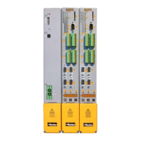
The shielded cables must be unbroken and grounded to a copper bar using the cable clamps
connections as shown in the drawing (at 360º) in order to obtain a good conductivity.
Generally, the shield should be connected to each extremity. In certain circumstances, however,
control cable shields may be connected only to one end to eliminate mains hum that could interfere
with the control signal. Decide case by case as numerous factors must be considered. Adopt the
following general approach: if the screen is solely for shielding, connect to both ends. If current
flowing in the shield interferes with the shielded signals, connect to one end only.
The incoming cable must be connected to an earth terminal trough a screw to ensure proper contact
between screen and earth.
Keep the power side (drive) and control side (PLC or NC) physically separated by isolating metal
mounting plates. Inside the electrical cabinet, the two plates must be connected through a copper
strap.
4.1.3 General suggestions on cable connections
Avoid routing noise emitting cables in parallel with "clean" cables
Avoid parallel cables, especially in the vicinity of the filter (ensure physical separation)
Avoid cable loops (keep cables as much short as possible and close to the common potential).
In particular, keep the main cables separate from motor cables.
If the motor is of the embedded brake type, keep the 24Vdc brake cables separate from the other
cables (resolver and motor).