20
start
end
start
end
frame
exposure (first row)
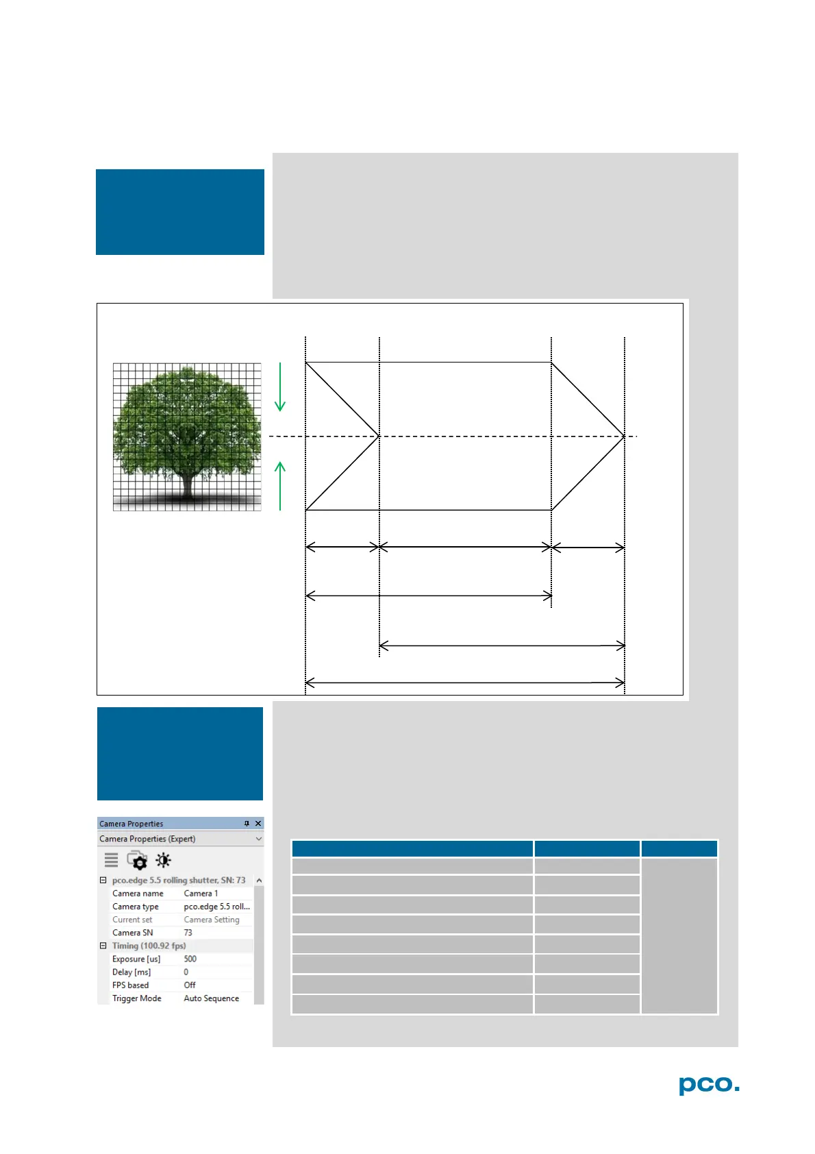
6.3.2 ROLLING SHUTTER
In Rolling Shutter mode the pixel reset and exposure start is carried
out row by row. Each row has the same exposure time, but a different
start and end of exposure. The pco.edge image sensor consists of
two discrete halves, which are exposed and read out simultaneously,
i.e. from the outside to the center by default. Within one row, the
exposure starts simultaneously for all pixels.
General Timing Diagram
The exposure time of each row starts with the corresponding reset of
the row. Then after a predefined time, the exposure is stopped. The
light induced accumulated charge carriers of the pixels in a row are
recorded into memory in a low noise (readout) mode. This results in
the total image appearing in memory corresponding to the row
readout.
Timing
0 … 1 s
pco.edge 4.2 LT USB 3.0
100 µs … 10 s
pco.edge 4.2 USB 3.0
100 µs … 20 s
Camera Link
pco.edge 4.2 Camera Link HS
100 µs … 10 s
pco.edge 5.5 USB 3.0
500 µs … 2 s
pco.edge 5.5 Camera Link
500 µs … 2 s
pco.edge 5.5 Camera Link HS
500 µs … 2 s
frame
The available Rolling
Shutter readout modes
see chapter 6.9.3.
The
exposure and
delay time can be
adjusted in steps of
one line time (see 1.2).
 Loading...