15192 Triton Lane
Huntington Beach, CA 92649
Office Tel: 714-892-3400
Hotline Tel: 714-891-6533
www.ppedm.com
This document is the property of PPedm Corp. and contains proprietary and/or patented information and may not be reproduced in
part or in whole without the express written permission of the company. Perfect Point logo, Perfect Point
TM
and E-Drill
®
are
trademarks of PPedm, Corp. US and worldwide patents pending.
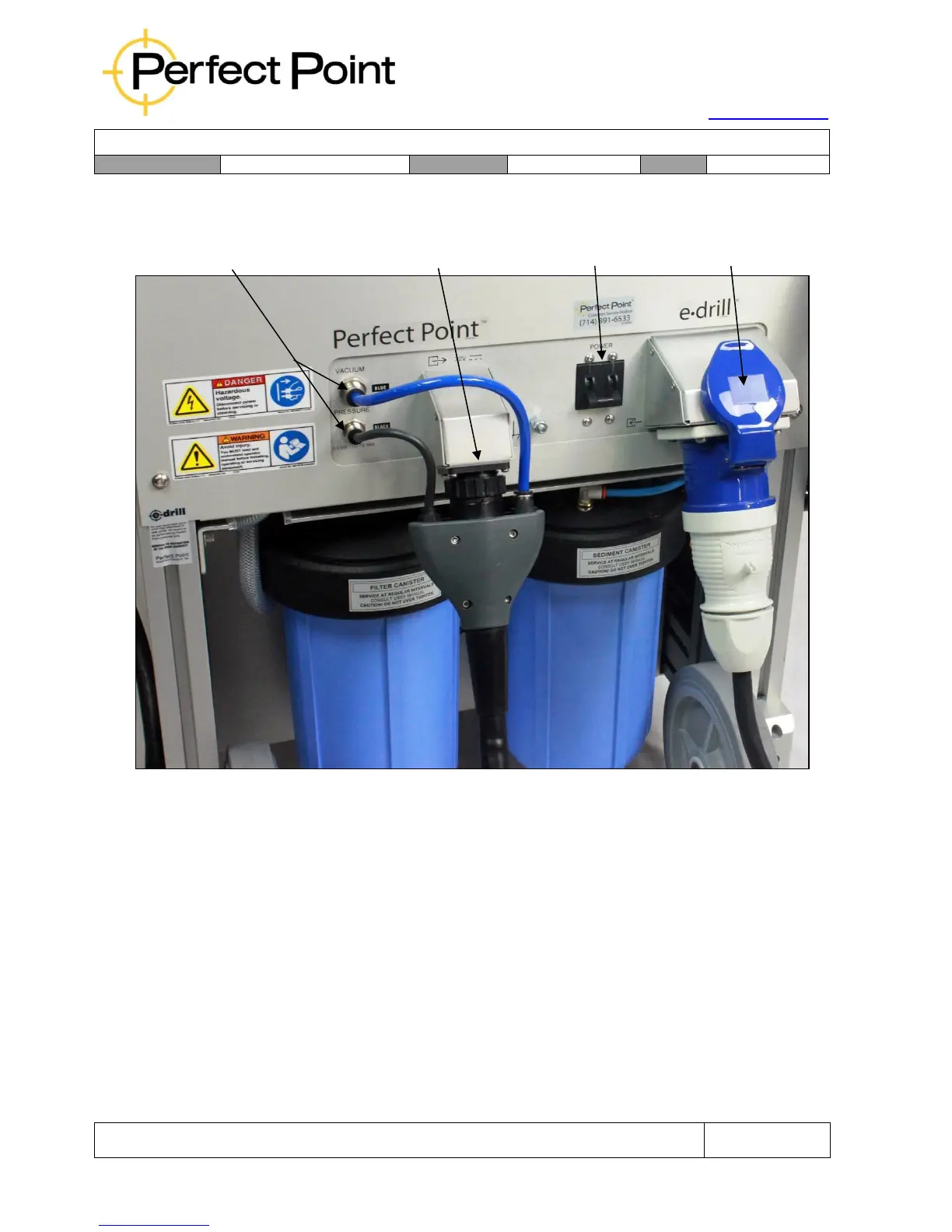
Mobile Service Unit – Rear Connections
Connection of the various components together is self-evident. However certain key
points should be noted:
1.
The hand-tool connector installs in one vertical orientation, with the blue
Vacuum dielectric connector at the top, and the black Pressure dielectric
connector at the bottom (matching the cabinet connections). The black
electrical connector locking bezel must be twisted until a definite click is felt.
The Touch-Screen Display connection (on the side of the unit at the top) also
installs in only one orientation and includes a locking bezel.
2.
When removing the hand-tool, the bezels around the Push-To-Connect™
fluid fittings on the Mobile Service Unit and Umbilical Cable must be pushed
in to release the tubes.