15192 Triton Lane
Huntington Beach, CA 92649
Office Tel: 714-892-3400
Hotline Tel: 714-891-6533
www.ppedm.com
This document is the property of PPedm Corp. and contains proprietary and/or patented information and may not be reproduced in
part or in whole without the express written permission of the company. Perfect Point logo, Perfect Point
TM
and E-Drill
®
are
trademarks of PPedm, Corp. US and worldwide patents pending.
5.0
APPENDIX 2. Adapter Charts and Cross Reference Data:
The following tables, charts and cross references are supplied to provide the user with
additional information to assist with proper configuration of the E-Drill system for a particular
fastener removal project.
5.1
Electrodes:
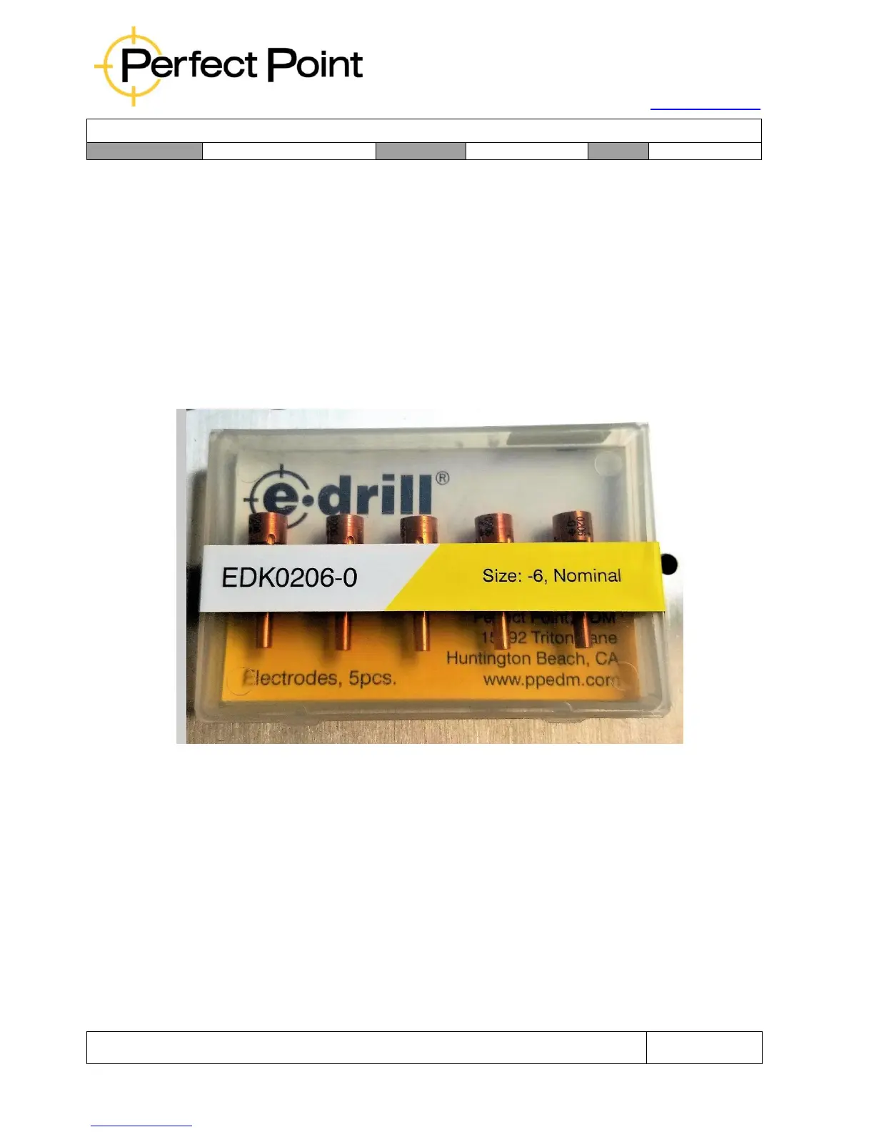
Electrode Kits are packaged in quantities of 5 each. Each package is identified with
colored card stock for quick identification of the size range. The packaging also
provides protection for the electrodes, which may be dented or bent with rough
handling.
Standard Electrode Packaging (5 each)
5.1.1
Electrode Information:
Electrodes come in a range of standard, first, and second, oversize. Each
size is identified by a color and a “dash” size. The following chart depicts the
Electrode size range. Each material is used for specific fastener material
removal. Refer to the Operator Hand Held Terminal for recommended
Electrode use.