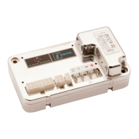
PG DRIVES TECHNOLOGY I-DRIVE TECHNICAL MANUAL – TRUCHARGE MODULE
5.3 Controller Connections
TruCharge Module Type TruCharge Module Connector Function TruCharge Interface
Inset 1 Switched B+ Pin 5
Inset 2 Status Indicator Pin 10
Inset 3 0V Pin 13
Surface 1 Switched B+ Pin 5
Surface 2 Status indicator Pin 10
Surface 3 0V Pin 13
Surface 4 ESD --
5.4 ESD Connection
5.4.1 Surface Mount Variant
This is an optional connection and may not be required, refer to
Section 6.2 for details.
If the connection is required then connection point 4 in the Molex ‘Mini-fit Jr’ 4 way connector must be utilized
5.4.2 Inset Mount Variant
This is an optional connection and may not be required, refer to
Section 6.2 for details.
If the connection is required there are two methods available. Firstly, a solder hole for wires or electrical suppression components.
Secondly, if screws are used to secure the TruCharge Module, then a ring terminal can be used.
6 Electromagnetic Compatibility (EMC)
The controller has been tested to allow compliance with EN12895:2000. The guidelines in this section will help you to make sure
that your machine installation will easily meet the requirements of the directive. You should consider EMC and perform relevant
tests as early as possible in the design phase.
6.1 Immunity and Emissions
Refer to the
Electromagnetic Compatibility section earlier in this technical manual.
6.2 Electro-Static Discharge (ESD)
The control panel module is the most vulnerable area on the machine to electro-static discharges. These discharges may cause
disruption of operation or even permanent damage. The TruCharge Module incorporates extensive protection against ESD;
however, you should follow the precautions set out in
Chapter 2 to prevent high levels of energy entering the machine’s
electronic system.
• The tiller module has a connection point, ESD; this can be used to provide an ESD drain path. The path
should be via a varistor connected between the ESD pin and the machine’s metalwork. A suitable device is
manufactured by Harris, type GE-MOV V82ZA2.
SK76977-07 101

 Loading...