I-DRIVE TECHNICAL MANUAL – INSTALLATION PG DRIVES TECHNOLOGY
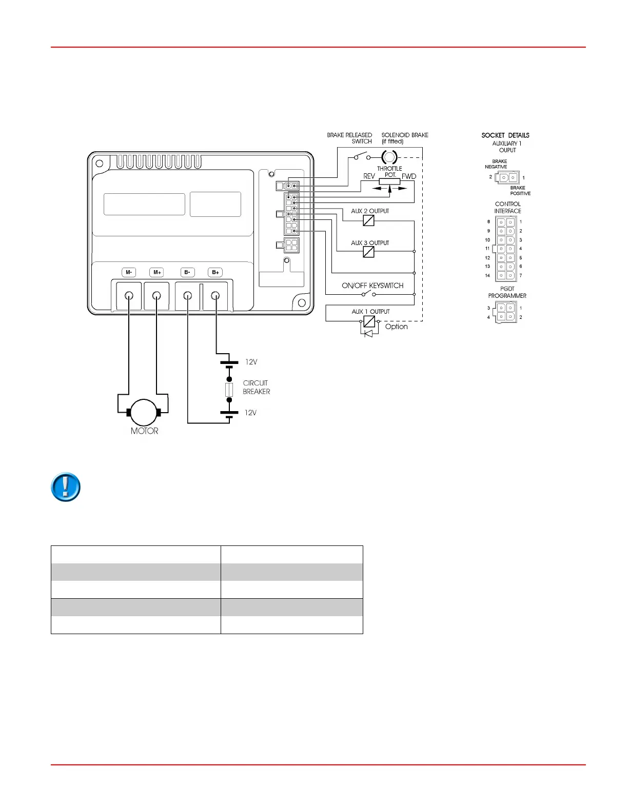
3.1.2 Wiring Configuration i140 & i180
A suitable suppression diode should be fitted across an Aux 1 Output relay coil, as shown above.
3.2 Connectors & Connector Kits
Battery & Motor Connectors
i24-45, i36-45, i24-70 & i36-70 0.25” 6.35mm Faston spade
i24-140, i36-140, i24-180 & i36-180 M6 screw terminals
Molex Connectors
All i-Drive family variants PGDT kit reference - D50319
3.2.1 Motor And Battery
3.2.1.1 i45 & i70
The battery and motor connections on the i45 and i70 controllers use 0.25” 6.35mm Faston type terminals. The mating female
parts should be sourced from a reputable manufacturer or supplier and these parts must be tested for suitability by the machine
manufacturer.
SK76977-07 30

 Loading...