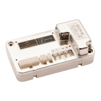
PG DRIVES TECHNOLOGY I-DRIVE TECHNICAL MANUAL – SPECIFICATIONS
1 Electrical Specifications
Version i24-45 i24-70 i36-45 i36-70 i24-140 i24-180 i36-140 i36-180
Supply Voltage 24Vdc 24Vdc or 36Vdc 24Vdc 24Vdc or 36Vdc
Operating Voltage 16 – 30Vdc 16 – 45Vdc 16 – 30Vdc 16 – 45Vdc
Peak Voltage 35Vdc 45Vdc 35Vdc 45Vdc
Reverse Battery Voltage 40Vdc 60Vdc 40Vdc 60Vdc
Auxiliary 1 1.25 max. sink
Auxiliary 2 800mA max. sink* 420mA max. sink* 1A max. sink
Auxiliary 3 800mA max. sink* 420mA max. sink* 1A max. sink
Status Output Programmable 12V, 50mA sink or source
Inhibit Input Programmable polarity
Output Current 45A 70A 45A 70A 140A 180A 140A 180A
PWM Frequency 20kHz + / - 1%
Power Connection 6.35mm (0.25”) Faston spade M6 screw terminals
Brake Connection 2-way Molex Mini-fit Jr
Programmer Connection 4-way Molex Mini-fit Jr
Tiller Connection 14-way Molex Mini-fit Jr
Moisture Resistance Electronics to IPX5 / Connections to IPX4 with iCover
Operating Temperature -25°C to +50°C
Storage Temperature -40°C to +65°C
Safety Multiple hardware & software strategy designed to EN60335/2/72
EMC Susceptibility Tested at 30V/m to EN12895:2000
EMC Emissions To EN12895:2000
ESD IEC 61000-4-2
*These values will be lower if both outputs are operated simultaneously and/or Aux 3 Output is PWM. Refer to
Chapter 2 for details.
SK76977-07 115

 Loading...