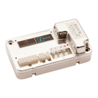
I-DRIVE TECHNICAL MANUAL – INSTALLATION PG DRIVES TECHNOLOGY
When suitably programmed, the switch is actuated AND the controller is in reverse drive, the Belly Button mode is initiated. This will:
Instantly reduce drive to 0%.
Accelerate in the forward direction to the programmed Belly Button Speed within 0.5s.
Drive forwards at the programmed Belly Button Speed until the switch is released or if the switch is not released, for a
period set by the programmed Belly Button Time.
Decelerate from the Belly Button Speed to a halt in 1s.
Exit Belly Button mode and resume normal operation once the next throttle signal is received.
The throttle command must be allowed to reset before new commands can be accepted.
Once initiated, the Belly Button mode will complete this sequence regardless of throttle commands.
The machine manufacturer is responsible for ensuring that the wiring of the Belly Button switch
and the programming of the Belly Button parameters are suitable for the intended application.
PGDT accepts no liability for losses of any kind arising from the incorrect wiring or programming
of the Belly Button function.
4.3 Fused B+ Supply
Pin 7 is a battery positive supply for the keyswitch circuit. The output has a self resetting fuse internally fitted. PGDT recommend
that no more than 3A is drawn from this output.
This connection should have no external capacitance connected to it and care should be taken not
to exceed the fuse rating if lights or other auxiliary functions are connected.
4.4 On/Off Switch
Pin 5 is the On/Off switch input to the i-Drive.
Due to the i-Drive’s low current drain when in the off state, the positioning of large capacitors on the On/Off line, between pins 5 &
7, could have a detrimental effect on the controller’s ability to switch off and on.
It is the responsibility of the machine manufacturer to test the effectiveness of the On/Off switch.
4.5 Status Indicator
This output controls either a PGDT TruCharge type status indicator or a single bulb (or LED) type Status Indicator.
If you are using a PGDT TruCharge indicator, the data connection must be to pin 10.
SK76977-07 38

 Loading...