I-DRIVE TECHNICAL MANUAL – INSTALLATION PG DRIVES TECHNOLOGY
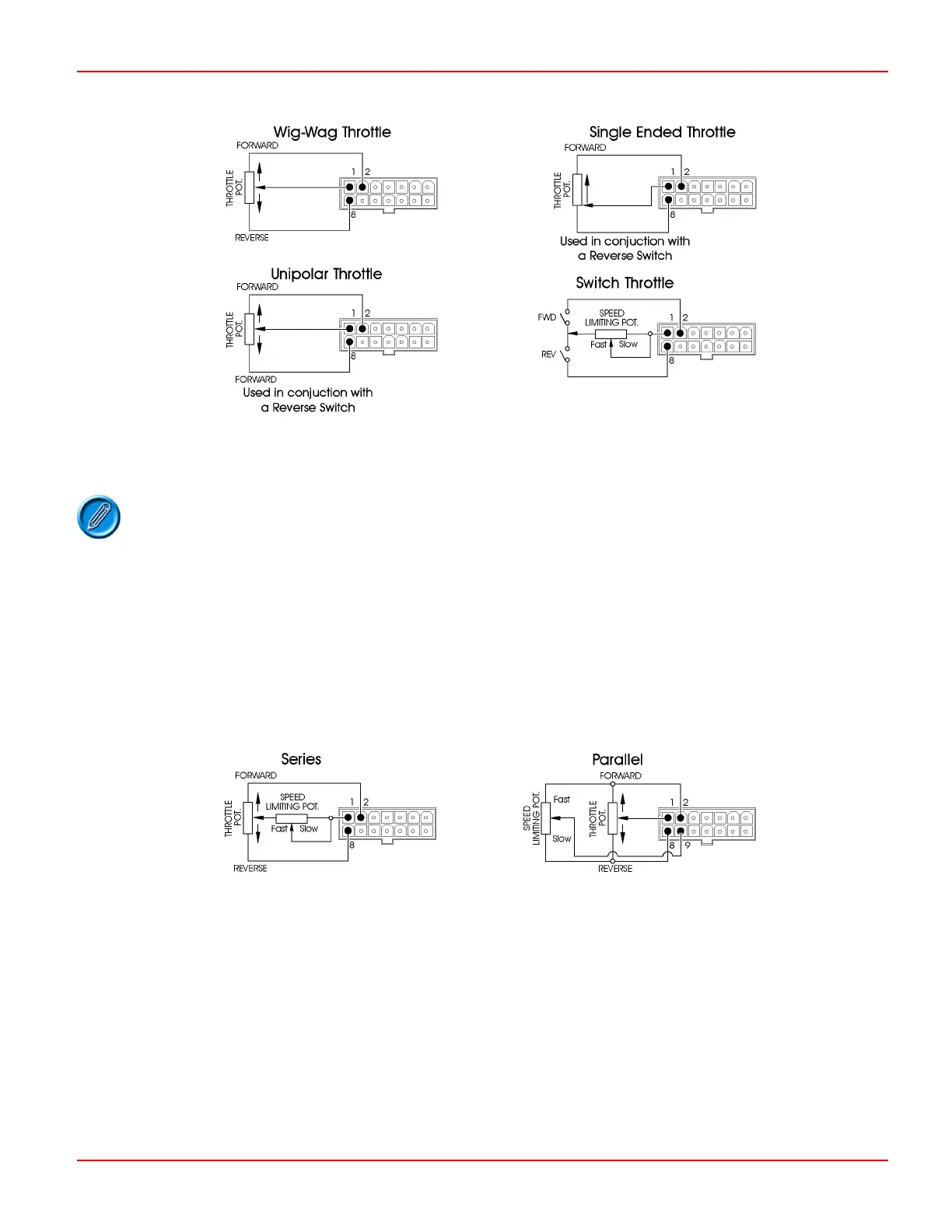
If a switch operated throttle is required, the parameter
Throttle Type must be set to Wig-wag and the parameter Throttle
Reference Test
must be set to Off.
Other factory programmed throttle inputs are available, e.g. an input configuration that accepts
signals in the range of 0-5V. If this configuration is used, a 10kΩ resistor must be connected in
series with the throttle wiper and the
Throttle Reference Test must be set to ‘Off’.
4.2 Speed Limiting Potentiometer / Belly Button Input
4.2.1 Speed Limiting Potentiometer Configuration
A speed limiting potentiometer may be connected in two ways.
In series with the throttle potentiometer wiper.
In parallel with the throttle potentiometer, through pin 9.
The illustration shows both connection variants with a wig-wag throttle.
If a series type connection is made a value of 25kΩ will result in the machine driving at 30% of maximum speed.
If a parallel type connection is made a potentiometer of 100kΩ ± 20% value should be used. The potentiometer should be fitted
so that its wiper is connected to the throttle high reference when the potentiometer is in the ‘fast’ position. The effect of the
potentiometer is explained in the section table.
When a parallel type connection is made the i-Drive should be programmed as follows.
SK76977-07 36

 Loading...