PG DRIVES TECHNOLOGY I-DRIVE TECHNICAL MANUAL – INSTALLATION
Continuous Means the Output is active the entire time the control system is powered up.
Forward Traction Means the Output is only active when the machine is driving forwards.
Traction Means the Output is only active when the machine is driving.
Reverse Traction Means the Output is only active when the machine is driving in reverse.
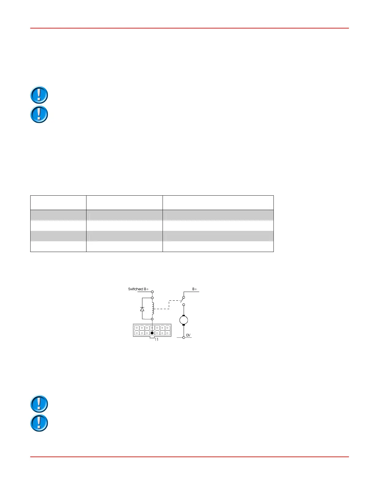
i45 & i70 controllers should be fitted with a suitable suppression diode, as shown above.
The Aux 2 relay coil should be connected to ‘Switched B+’, not the battery positive terminal.
4.9 Auxiliary 3 Output
Pin 11 is a self-protected output, which can be programmed to operate a range of functions depending on the machine’s
specifications. The parameter that must be programmed is
Auxiliary 3 Output Mode.
The current rating of pin 11 is dependent on the model of i-Drive and will be altered if the Auxiliary 2 Output is operated at the
same time and/or if the Aux 3 Output is PWM.
Model Pin 11 - Aux 3 Output only Pin 11 - Simultaneous Aux 2 Output
operation and/or Aux 3 Output PWM
i24-45 & i24-70 800mA 500mA
i36-45 & i36-70 420mA 340mA
i24-140 & i24-180 1A 1A
i36-140 & i36-140 1A 1A
Pin 11 will be active depending on how the parameter
Auxiliary 3 Output Mode is programmed. The four modes, which should
be used to control an auxiliary motor, are Continuous, Forward Traction, Reverse Traction and Traction.
Continuous Means the Output is active the entire time the control system is powered up.
Forward Traction Means the Output is only active when the machine is driving forwards.
Reverse Traction Means the Output is only active when the machine is driving in reverse.
Traction Means the Output is only active when the machine is driving.
i45 & i70 controllers should be fitted with a suitable suppression diode, as shown above.
The Aux 3 relay coil should be connected to ‘Switched B+’, not the battery positive terminal.
SK76977-07 43
 Loading...
