PG DRIVES TECHNOLOGY I-DRIVE TECHNICAL MANUAL – PROGRAMMING
8.4 Current Foldback Temperature
The parameter Current Foldback Temperature sets the temperature at which the i-Drive starts to reduce its maximum current
capability to protect the controller. The temperature is measured at the i-Drive’s heatsink.
Current Foldback Temperature Adjustable between 0°C and 80°C in steps of 1°C.
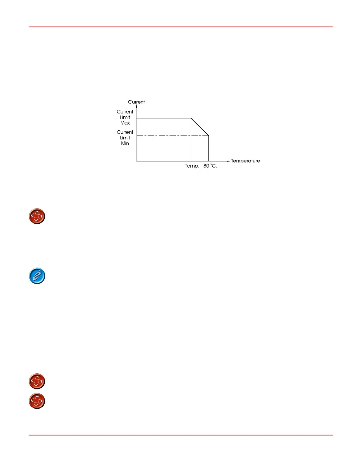
The following graph shows the operation of this function.
If the i-Drive’s internal temperature reaches the value set by Current Foldback Temperature, the maximum current output will be
reduced from the value set by Current Limit Max. The reduction will be linear to a value set by Current Limit Min. at a fixed internal
temperature of 80°C.
The value of Current Foldback Temperature should never be set higher than 80°C. PGDT accepts
no liability for losses of any kind arising from failure to comply with this condition.
8.5 Controlling a Machine on a Slope
The i-Drive controller contains a set of anti roll-back parameters, which allow smooth precise control, especially when starting and
stopping on inclines. This section explains how to set this group of co-relational parameters.
Motors and gearboxes due to their construction, normally display evidence of gear backlash. This
will be evident by a small amount of wheel rotation as the solenoid brake is engaged/disengaged.
8.5.1 Motor Compensation
This matches the controller to different motor types in order to achieve optimal performance and control, especially regarding
anti-rollback and braking on gradients. PGDT recommend that you set this value to 60% of the resistance of the motor armature
and all connectors and cables to it.
Motor manufacturers should be able to supply figures for armature resistance, and typical cable and connectors would be
about 40mΩ.
You can set this value between 0 and 1250mΩ in steps of 5mΩ.
If you do not have the exact values of resistance, some basic test driving can be used to determine the value required. See
section
Set-up Procedure for details.
Motor Compensation should never exceed 60%.
The machine manufacturer is responsible for ensuring that the controller is matched to the motor
resistance. Failure to do this may result in poor control characteristics, which in extreme
instances can make a machine uncontrollable and potentially unsafe. PGDT accepts no liability for
losses of any kind arising from failure to comply with this condition
.
SK76977-07
7

 Loading...