I-DRIVE TECHNICAL MANUAL – INSTALLATION PG DRIVES TECHNOLOGY
4.10 0 Volts
Pin 13 provides the battery negative connection to the machine’s tiller. This pin has a current rating of 3A via an internal self-
resetting fuse.
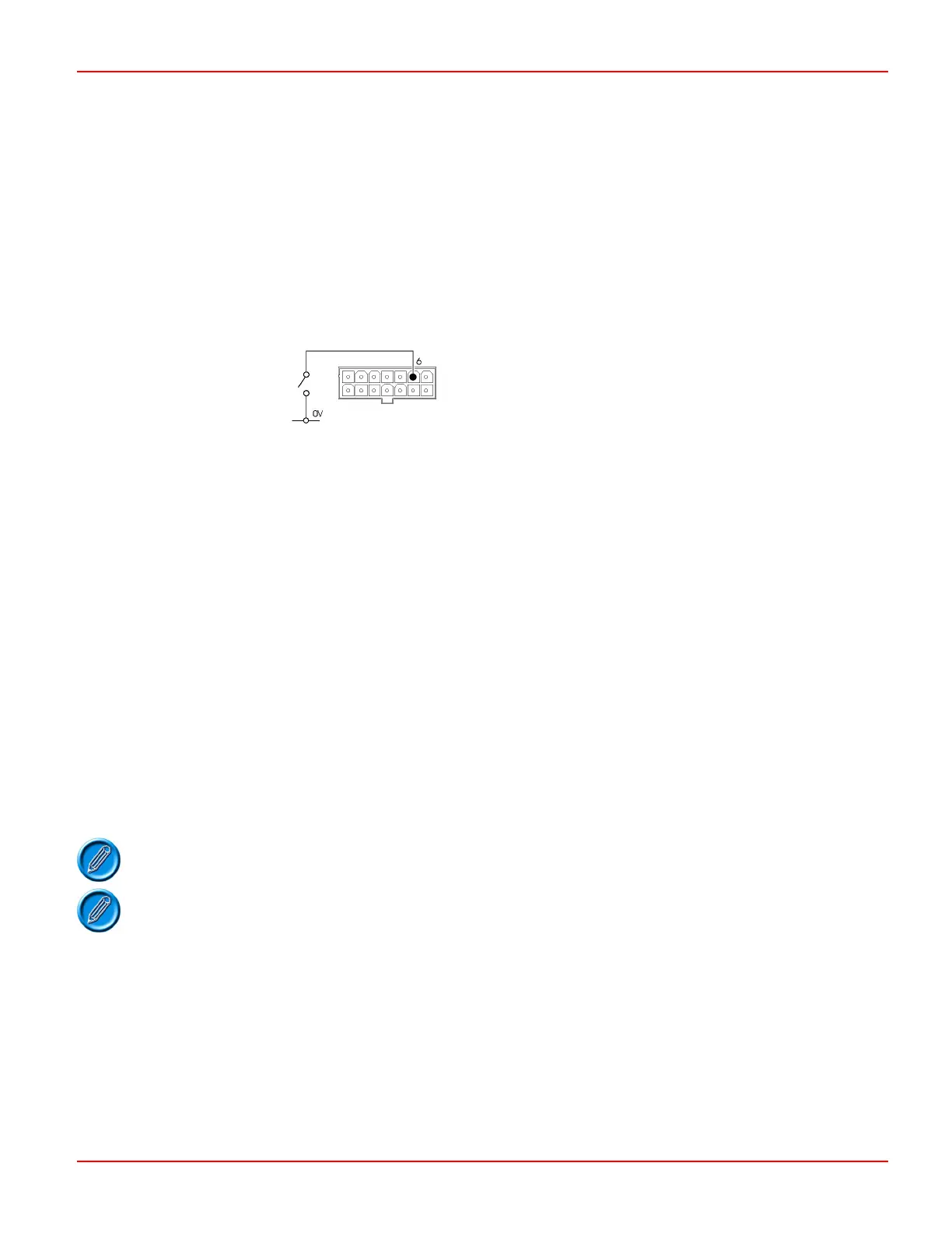
4.11 Inhibit 1 / Forward Direction Switch
This input is located on pin 6 of the 14-way tiller connector. The function of the input is programmable and can be changed
using the
Direction Switches parameter. Refer to Chapter 3 for details.
4.11.1 Inhibit 1
Each Inhibit input has been designed to either inhibit a specific function or control an auxiliary function such as a brush or
vacuum motor. The Inhibits can be used to either limit the maximum speed of the machine, stop it completely or in the case of
an auxiliary output, stop and start the output device.
See the example in Section 4.11.6.
Inhibit 1 input has 5 programmable parameters.
Inhibit 1 Debounce.
Inhibit 1 Mode.
Inhibit 1 Target.
Inhibit 1 Speed.
Inhibit 1 Operation.
4.11.2 Inhibit 1 Debounce
This parameter sets the amount of time a connection to Inhibit 1 must be stable before it is interpreted as a valid condition. This
parameter is particularly useful for interlock switches such as a seat switch, which can bounce momentarily as the operator
passes over bumpy terrain.
The parameter is programmable between 0s and 5s in 0.5s steps.
If set to 0, then the normal inherent debounce will be applied to the input.
Inhibit Debounce functionality is standard on i140 and i180 only. Please contact PGDT if this
functionality is required on your i45 or i70 application.
4.11.3 Inhibit 1 Mode
This parameter refers to the state in which the inhibit is active.
SK76977-07 44

 Loading...