PG DRIVES TECHNOLOGY I-DRIVE TECHNICAL MANUAL – INSTALLATION
The maximum current rating of the output is 50mA; you must ensure that the indicator does not draw more current than this
value.
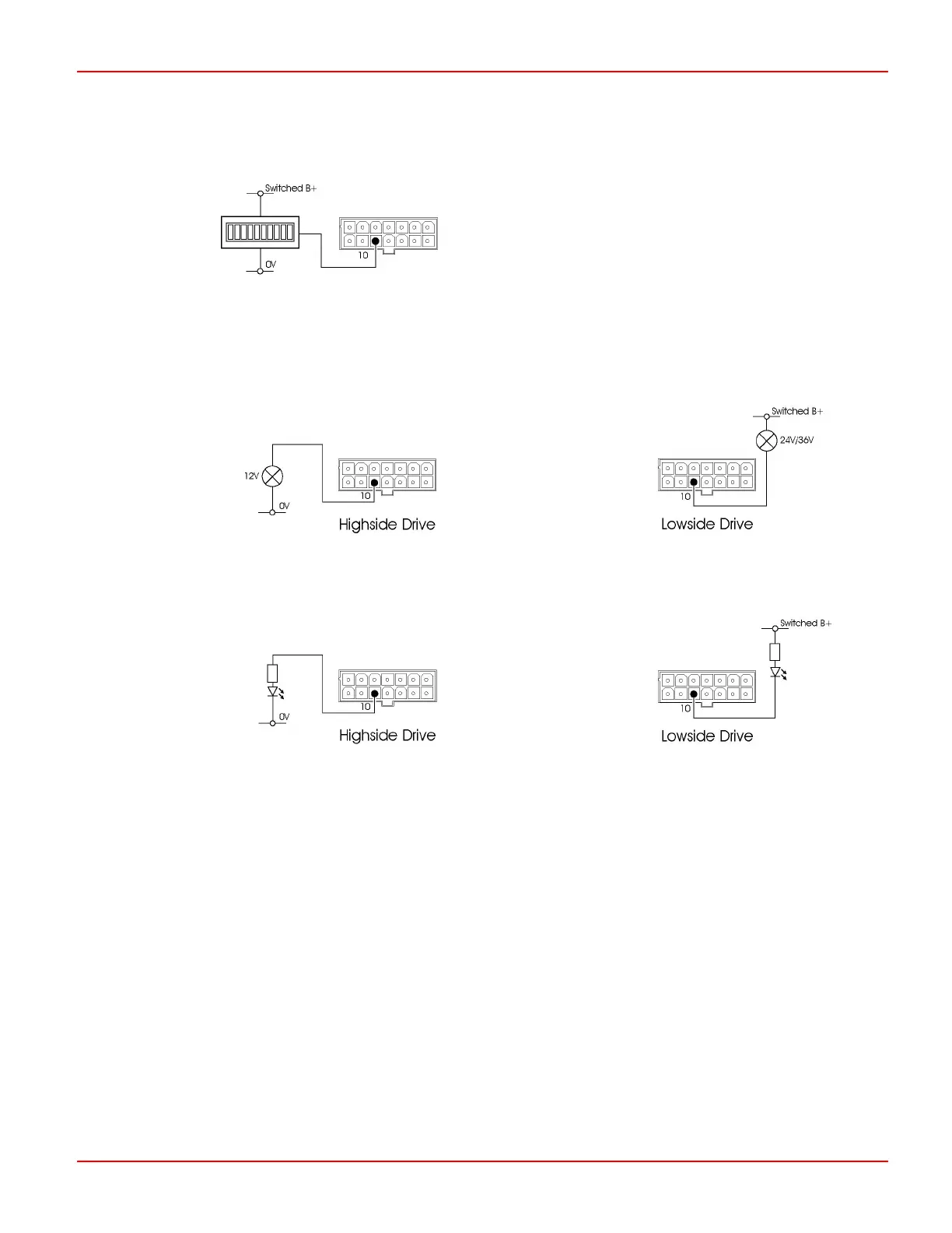
If you are using a bulb, the bulb can be connected directly between pin 10 and 0V (Highside) or pin 10 and switched B+
(Lowside). The bulb must be 12V with a maximum rating of 600mW when connected Highside and 24V / 36V with a maximum
rating of 600mW when connected Lowside.
If you are using an LED, it is connected between the same points but you must provide a series connected current limiting
resistor.
If you are using an Analogue 12V Status Indicator, it is must be connected between pin 10 and 0V.
For each connection and indicator type the controller will require programming to suit. The parameter that will require adjustment
is
Status Output Type.
This will require programming to one of the following:
TruCharge Suitable for Lamp and LED Status Indicators on Highside Drive connections and the TruCharge Status
Indicator.
Sink Suitable for Lamp and LED Status Indicators on Lowside Drive connections.
Analogue Suitable for Analogue 12V Status Indicator.
4.5.1 Status Indicator Diagnostic Setting
For each Status Indicator type the controller will require programming to suit. The parameter that will require adjustment is
Diagnostic Flash Sequence.
SK76977-07 39
 Loading...
