I-DRIVE TECHNICAL MANUAL – TRUCHARGE MODULE PG DRIVES TECHNOLOGY
3.3 Inset Variant
3.3.1 Fixing
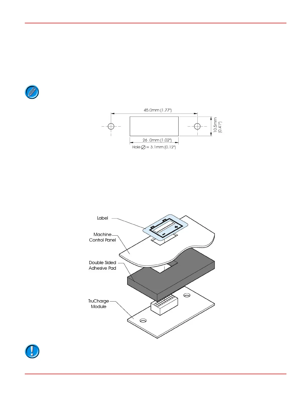
The machine’s control panel should be fitted with holes as suggested in the diagram below.
The supplied double-sided adhesive pad should be used to secure the TruCharge Module to the machine’s control panel. See
the following illustration.
If the adhesive pad is being used to attach the TruCharge Module then the screw holes either side
of the central rectangle will not be required.
Alternatively M3 (4-40 UNC) hardware can be used. The height of the display from the printed circuit board is 8.0mm (0.31").
Suitable spacers should be used so that the display is fixed slightly below the machine’s control panel. Ensure that the metallic
fixing hardware (nuts, washers etc.) do not touch the conductive tracks on the printed circuit board.
3.3.2 Sealing
The module should be sealed against the ingress of water and dust by placing an adhesive waterproof overlay over the display
cut-out. The overlay should contain a suitably sized transparent window and the overall dimensions should be at least 36.0mm x
20.5mm (1.41" x 0.81").
The sealing label is only supplied with the TruCharge Module kit number D50066.
SK76977-07 98

 Loading...