I-DRIVE TECHNICAL MANUAL – INSTALLATION PG DRIVES TECHNOLOGY
This will require programming to one of the following:
None No diagnostic indication.
TruCharge PGDT diagnostic information. Refer to
Chapter 1 Section 8.
PG Suitable for Lamp or LED Status Indicators. The Status Indicator will flash the equivalent message of
the TruCharge display.
Refer to
Chapter 3 for details.
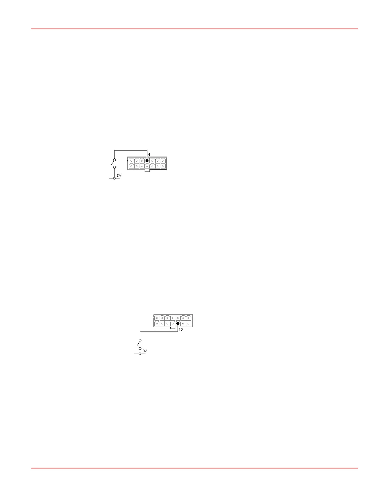
4.6 Slow/Fast Switch
Pin 4 is an input that can be used to limit the forward and reverse speeds, the forward and reverse acceleration and the forward
and reverse deceleration of the machine.
If pin 4 is connected to 0V the controller will drive using the programmed slow speed and rates. These speeds are listed below.
If pin 4 is open then the controller will drive using the programmed fast speed and rates. These speeds are listed as follows:
Forward Accel’n fast : xx slow: xx Forward Decel’n fast : xx slow: xx
Reverse Accel’n fast : xx slow: xx Reverse Decel’n fast : xx slow: xx
Max. Fwd Speed fast : xx slow: xx Min. Fwd Speed fast : xx slow: xx
Max. Rev Speed fast : xx slow: xx Min. Rev Speed fast : xx slow: xx
4.7 Reverse Switch / Auxiliary 3 Input / Reverse Direction Switch
4.7.1 Reverse Switch
Pin 12 is a connection for a reverse switch. This is required to select reverse drive, only if the controller is being used with single-
ended or unipolar throttle configurations.
The direction of drive is programmable and can be changed using the
Throttle Invert parameter. Refer to Chapter 3 for details.
With Throttle Invert set to Off, the drive will be in reverse if pin 12 is connected to 0V.
With Throttle Invert set to On, the drive will be forwards if pin 12 is connected to 0V.
4.7.2 Auxiliary 3 Input
If a wig-wag throttle is fitted to the machine then this input can be used to control the Auxiliary 3 Output. In this instance, the
Auxiliary 3 Input parameter sets the function of the pin. Refer to Chapter 3 for details.
If set to None, the output will be active as per the Auxiliary 3 Output Mode.
If set to Reverse Switch, the Auxiliary 3 Output will only be active when the switch is closed.
SK76977-07 40

 Loading...