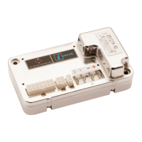
PG DRIVES TECHNOLOGY I-DRIVE TECHNICAL MANUAL – DIAGNOSTICS
1 Introduction
The primary objective of this chapter is to assist service personnel in finding the likely area of a detected fault within the whole
electrical system. It is important to realize that even though the i-Drive is signalling a trip, it may not be the control system itself
that is defective. This is because the i-Drive is able to detect problems in other electrical components (motors, batteries, solenoid
brakes, etc.) or, more importantly, the wiring to them.
Using this guide, it is possible to define a trip as belonging to one of 10 types. Once the type has been established, there are
suggestions as to what the possible cause may be.
The guide should only be used to decide the starting point of your own diagnosis, as it is possible for the controller to indicate a
fault in another component, even though the controller itself may be defective. Nevertheless, experience has shown that
connectors and wiring are the major cause of machine problems, so it is necessary to examine these more vulnerable areas first.
Diagnostics should only be conducted by electronic service professionals with in-depth knowledge
of PGDT electronic control systems. An incorrect or badly effected repair could result in an unsafe
set-up of a machine. PGDT accepts no liability for losses of any kind arising from an incorrect or
badly effected repair.
1.1 Diagnostic Procedure
For efficient and effective diagnosis the following basic steps should be taken:
• Observe the Status Indicator or use a PGDT programmer to confirm the i-Drive is tripping or has tripped
intermittently in the past.
• Refer to the trip table shown in this chapter.
• Refer to the possible cause shown in the table and carry out the recommended investigative and corrective
action.
1.2 Detecting A Trip Has Occurred
Firstly, observe the Status Indicator. Depending on the machine model, the status indicator may be a single lamp (or LED) or a
TruCharge battery gauge. Both types indicate the status of the controller and will flash to indicate a trip. Refer to
Chapter 1,
Section 8
for details on how to interpret this information.
If the Status Indicator shows the controller is tripping, plug a PGDT programmer in to the 4-way Molex connector fitted to the i-
Drive. Note the trip code and refer to the table in Section 2.
If the Status Indicator is not denoting a trip but you suspect an intermittent problem, interrogate the controller’s diagnostic logs
with the programmer. Note the contents of the logs and refer to the table in Section 2 for assistance. Further information about
the diagnostic logs can be found in
Chapter 3, Section 12.
SK76977-07 87

 Loading...