Maintenance and Adjustments
61-900040-000 Rev. Date: 01/22 4-11
1. While it is not necessary to remove the
hood in order to perform this procedure,
removing the hood will improve access to
the buffer linkages but will require that the
hood be reinstalled to check the
adjustment. To remove the hood, unlatch
the oil compartment door latches,
disconnect the vacuum hose and remove
the waste tank, remove the cap from the
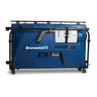
cleaner tank, remove the two screws
from each side of the hood as shown in Figure 4- 6, and lift the hood from the
frame. Set the screws aside.
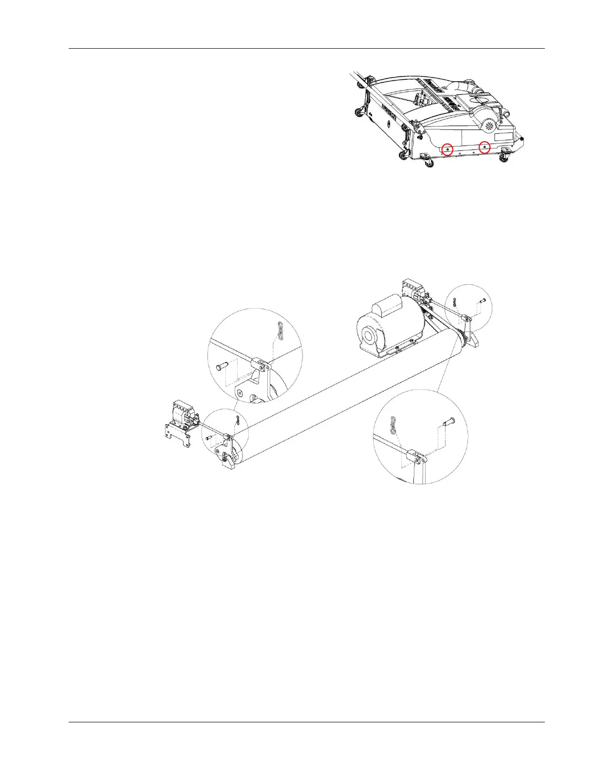
2. On each side of the oil tank, locate, remove, and set aside the clevis pins and
bowtie cotters for the buffer brush solenoids as shown in Figure 4- 7. To allow for a
more detailed view, all other components have been hidden.
3. Position the linkage as shown in Figure 4- 8 on the next page.
To increase the buffer brush pressure, shorten each solenoid connecting rod by
turning the clevis clockwise.
To decrease the buffer brush pressure, lengthen each solenoid connecting rod
by turning the clevis counter-clockwise.
TIPS
Make only small incremental adjustments to the buffer brush position and repeat the
pressure test after each adjustment until the desired pressure is achieved.
Depending on how much adjustment is needed, the jam nut may need to be
loosened to allow for more travel of the linkage.