phyFLEX
®
-i.MX 6 [PFL-A-XL1-xxx
vi PHYTEC Messtechnik GmbH 2013 L-773e_2
Tables which describe jumper settings show the default position in
bold, blue text.
Text in blue italic indicates a hyperlink within, or external to the
document. Click these links to quickly jump to the applicable
URL, part, chapter, table, or figure.
References made to the phyFLEX-Connector always refer to the
high density samtec connector on the undersides of the
phyFLEX-i.MX 6 System on Module.
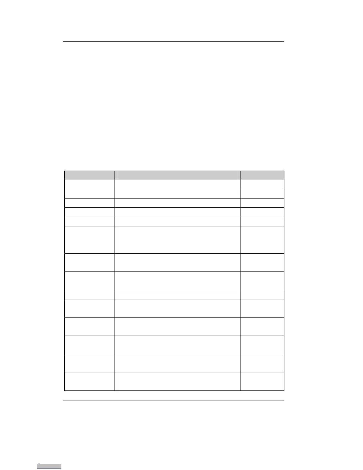
Types of Signals
Different types of signals are brought out at the phyFLEX-Connector.
The following table lists the abbreviations used to specify the type of a
signal.
Signal Type Description Abbr.
Power Supply voltage input PWR_I
Ref-Voltage Reference voltage output REF_O
Input Digital input I
Output Digital output O
IO Bidirectional input/output I/O
IPU Digital input with pull-up, must only
be connected to GND. (jumper or
open-collector output)
IPU
OC-Bidir PU Open collector input/output with pull
up
OC-BI
OC-Output Open collector output without pull up,
requires an external pull up
OC
5V Input PD 5 V tolerant input with pull down 5V_PD
LVDS Input Differential line pairs 100 Ohm
LVDS level input
LVDS_I
LVDS
Output
Differential line pairs 100 Ohm
LVDS level output
LVDS_O
LVDS IO Differential line pairs 100 Ohm
LVDS level bidirectional input/output
LVDS_I/O
TMDS
Output
Differential line pairs 100 Ohm
TMDS level output
TMDS_O
USB IO Differential line pairs 90 Ohm USB
level bidirectional input/output
USB_I/O
Downloaded from Arrow.com.Downloaded from Arrow.com.Downloaded from Arrow.com.Downloaded from Arrow.com.Downloaded from Arrow.com.Downloaded from Arrow.com.Downloaded from Arrow.com.Downloaded from Arrow.com.