Pin Description
PHYTEC Messtechnik GmbH 2013 L-773e_2
9
The numbered matrix can be aligned with the phyFLEX-i.MX 6
(viewed from above; phyFLEX-Connector pointing down) or with the
socket of the corresponding phyFLEX Carrier Board/user target
circuitry. The upper left-hand corner of the numbered matrix (pin
X1A1) is thus covered with the corner of the phyFLEX-i.MX 6. The
numbering scheme is always in relation to the PCB as viewed from
above, even if all connector contacts extend to the bottom of the
module.
The numbering scheme is thus consistent for both the module’s
phyFLEX-Connector as well as the mating connector on the phyFLEX
Carrier Board or target hardware, thereby considerably reducing the
risk of pin identification errors.
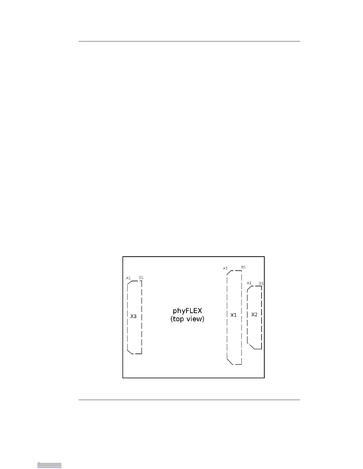
The following figure illustrates the numbered matrix system. It shows
a phyFLEX-i.MX 6 with all three SMT phyFLEX-Connectors on its
underside (defined as dotted lines) mounted on a carrier board. In
order to facilitate understanding of the pin assignment scheme, the
diagram presents a cross-view of the phyFLEX-i.MX 6 module
showing the phyFLEX-Connector mounted on the underside of the
module’s PCB.
Figure 4: Pinout of the phyFLEX-Connector (top view)
Downloaded from Arrow.com.Downloaded from Arrow.com.Downloaded from Arrow.com.Downloaded from Arrow.com.Downloaded from Arrow.com.Downloaded from Arrow.com.Downloaded from Arrow.com.Downloaded from Arrow.com.Downloaded from Arrow.com.Downloaded from Arrow.com.Downloaded from Arrow.com.Downloaded from Arrow.com.Downloaded from Arrow.com.Downloaded from Arrow.com.Downloaded from Arrow.com.Downloaded from Arrow.com.Downloaded from Arrow.com.Downloaded from Arrow.com.Downloaded from Arrow.com.Downloaded from Arrow.com.Downloaded from Arrow.com.Downloaded from Arrow.com.Downloaded from Arrow.com.Downloaded from Arrow.com.Downloaded from Arrow.com.