DA80F/DA95F AddressRight™ Printers Service Manual (SV61962 Rev. A)
5-53
Removal and Replacement • 5
DA95F (WF96) - Printer Parts Removal
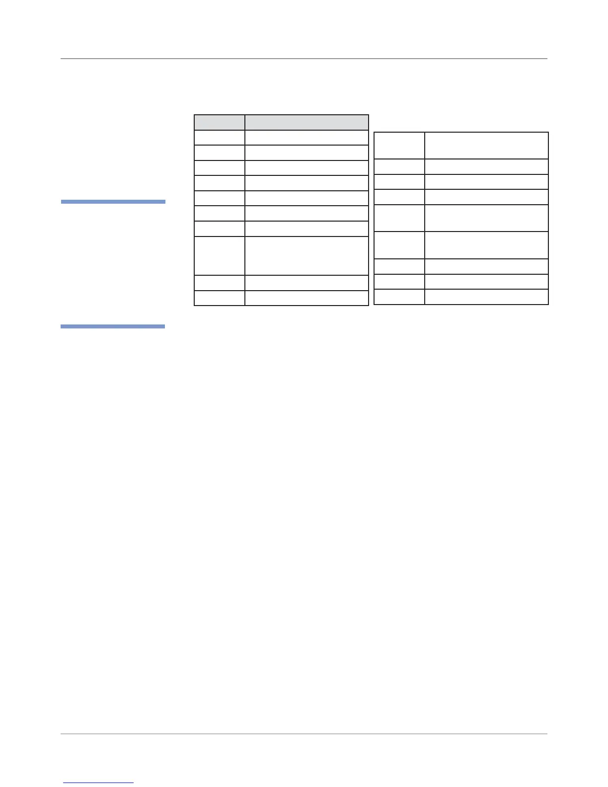
12. Install new board and reconnect the cables to the board as shown below.
5.30 Rear
Cover and Main
Processor
Board
(continued)
✍
TIP: Device name
is unique to each
printer’s main board.
Therefore, replacing
an existing main board
in the printer gives that
printer a new device
name.
Location Description
J1 Print Head 1
J2 Print Head 2
J3 Print Head 3
J4 Print Head 4 [DA95F only]
J5 Print Head 5 [DA95F only]
J6 Print Head 6 [DA95F only]
J11 W98x Series Stacker
J15 Feeder Motor, Feeder
Motor Encoder, Feeder
Sensors [DA95F only]
J18 LAN
J20 USB
13. Reassemble in reverse order.
NOTE: Every time the main processor board is changed or removed, the
printer must be powered down and powered on.
IMPORTANT! Be careful when re-connecting the ribbon print head
cables (J1 to J6) on the main processor board. Make sure each cable is
aligned straight before fully seating; otherwise, some pins may touch and
cause damage to the print head (Newport) boards inside the print head
assembly upon powering up.
J21 External High Speed
Feeder [DA95F only]
J23 Input Power
J25 LCD Display
J27 Transport Motor
J28 Exit Sensor Receiver
[DA95F only]
J29 Exit Sensor Emitter
[DA95F only]
J32 Paper Sensor Emitter
J33 Paper Sensor Receiver
J34 Shaft Encoder