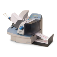
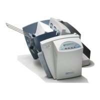
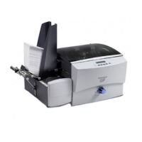
5 • Removal and Replacement
DA80F/DA95F AddressRight™ Printers Service Manual (SV61962 Rev. A)
5-1
This chapter contains parts removal instructions and is divided into two sec-
tions; one for the DA80F model and one for the DA95F model.
Tools Required
• Ball end square (quadrax) drives. Sizes used:
#0 for 4-40 screws
#1 for 6-32 screws
#2 for 8-32 screws
NOTE: Phillips head screwdrivers of the same size work but not as well if
you are at an angle.
• Allen wrenches (imperial standard sizes). NOTE: The extra small encod-
er Allen (.050 inch) is taped inside each printer.
• 5/16” imperial socket (for WF81)
• Cutters
• Pliers
• Feeler gauges
DA80F (WF81) Parts Removal
5.2 Rear Cover and Keyboard/LCD Display Board ......................... 5-3
5.3 Main Processor Board ............................................................... 5-4
5.4 Encoder Assembly .................................................................... 5-6
5.5 Paper Top Sensor Assembly (Emitter) ...................................... 5-9
5.6 Paper Bottom Sensor Assembly (Receiver) .............................. 5-9
5.7 Feeder Sensor Assembly (Emitter and Receiver) ................... 5-10
5.8 Front Bottom Cover Assembly ..................................................5-11
5.9 Transport Timing Belt .............................................................. 5-12
5.10 Feed Motor Timing Belt ......................................................... 5-13
5.11 Feed Roller Pulley and Feed Roller Assembly ...................... 5-14
5.12 Feed Motor Assembly and Encoder Harness Assembly........ 5-16
5.13 Transport Motor Assembly ..................................................... 5-18
5.14 H-Block Assembly (Media Separators) .................................. 5-20
5.15 Print Head Cables and Print Head Boards ............................ 5-21
5.16 Entry Idler Roller Arm ............................................................ 5-28
5.17A Feed Deck ............................................................................ 5-30
5.17B Front Plate Assembly ........................................................... 5-32
5.18 Transport (Metal Grit) Roller .................................................. 5-34
5.19 Exit (Rubber) Roller ............................................................... 5-35
5.20 Power Supply ........................................................................ 5-36
5.21 Print Head Access Door ........................................................ 5-38
5.1 List of
procedures