5-58 DA80F/DA95F AddressRight™ Printers Service Manual (SV61962 Rev. A)
5 • Removal and Replacement
DA95F (WF96) - Printer Parts Removal
5.35 Idler
Roller Support
(“Module B”)
Assembly and
Exit Sensor
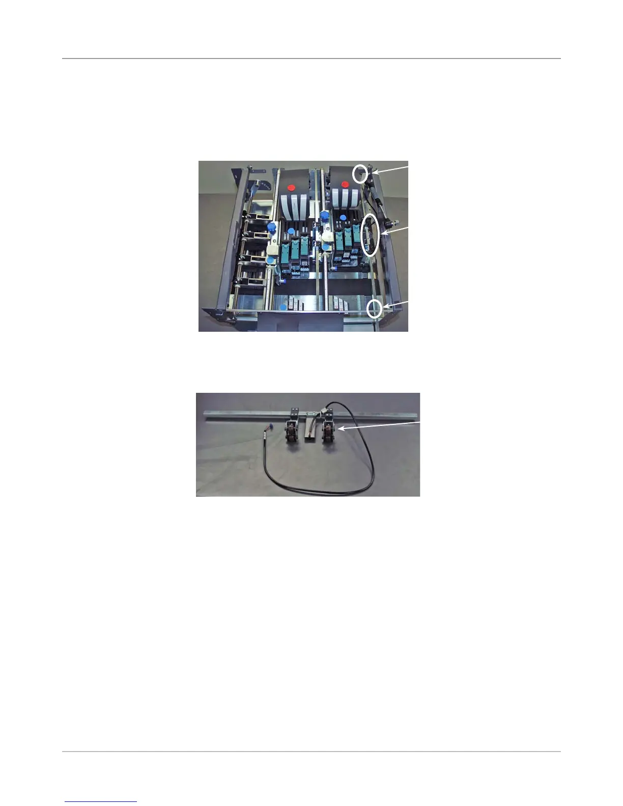
1. Remove the front cover assembly (see section 5.29) and rear cover (see
section 5.30).
2. Unfasten the four screws (two on either side, see figure below) and re-
move the idler roller support assembly.
3. If replacement of sensor is required, unfasten one screw holding exit sen-
sor to shaft and remove sensor emitter. Unplug P29 from main board and
thread harness through wire management devices.
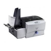
Idler Roller for
“Module B”
Idler Roller for “Module B” With Exit Sensor Emitter
4. Unfasten the two screws (one on either side) holding each idler roller to
its idler roller arm and remove idler roller.
5. Reinstall in reverse order.
Two Screws for Each Idler
Roller (8 screws total)
Two Screws
(obscured in
figure)
Two Screws
(obscured in
figure)