D-6 DA80F/DA95F AddressRight™ Printers Service Manual (SV61962 Rev. A)
Appendix D • Print Head Alignment
For DA95F Only
28 a. Make sure the printer is OFF LINE. To do this, press the ON LINE
key until the indicator light above the key goes out.
b. Access the Service Menu by holding down the Menu and minus (-)
keys simultaneously for two seconds. The Adjust Printing screen will
display.
c. Press Enter. The B. Print Head Adjust screen will display.
d. Follow steps 4-27 in Performing a Print Head Alignment, to perform
the horizontal and vertical alignment procedures for print head
module B.
IMPORTANT: Be sure to select the menu options for Heads 4 - 5
and 5 - 6. These are the print heads contained in module B.
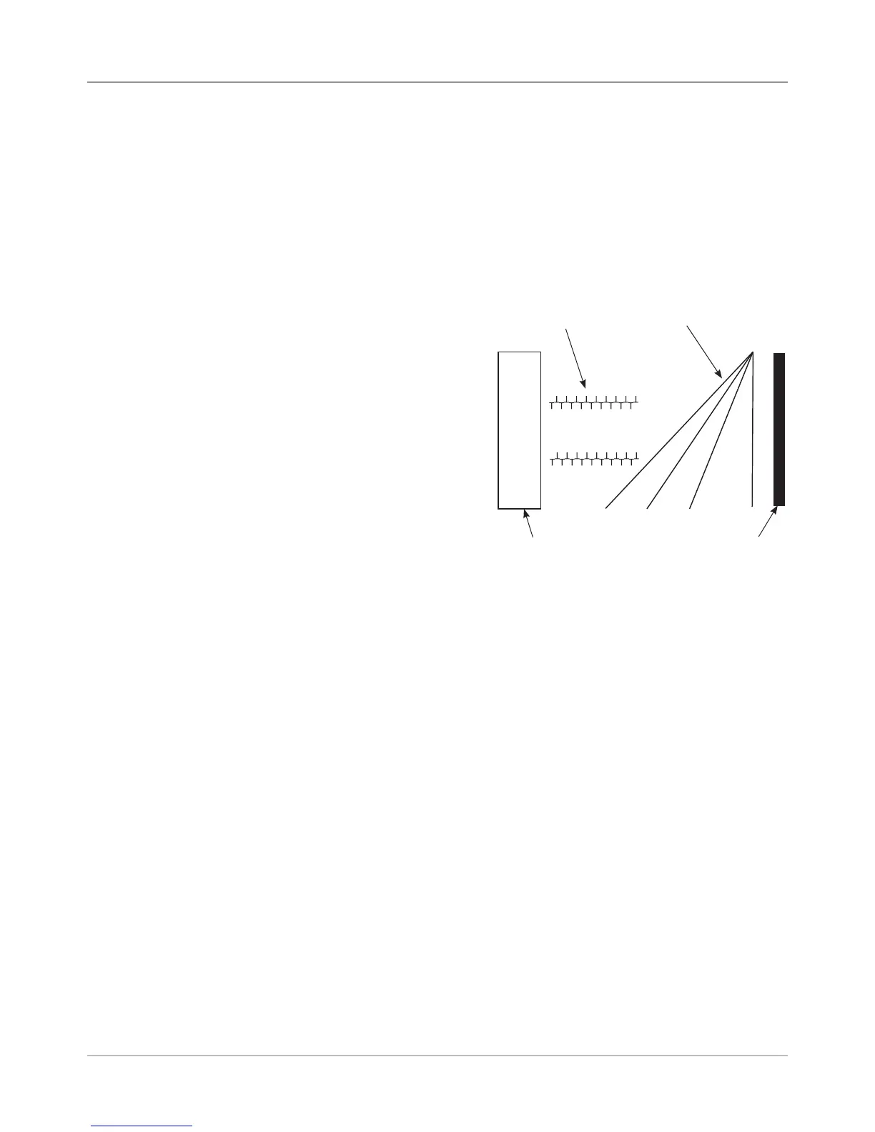
T's are touching
and aligned
.
Rectangle
is straight
Lines are straight and
unbroken
Rectangle is straight and
is .25 in (6.35 mm) from
right edge of test material.
Print Head
Alignment
Procedure
26. Scroll using the plus (+) and minus (-) keys to change the number on
the display. Press Enter. You have completed the Print Head Sensor
Alignment. Go to step 27 to print a test pattern
27. Ensure material (paper, envelope, etc.) is loaded in the printer. Press the
Test Env key. A test pattern will print. Verify that your test pattern looks
like the example provided.
DA80F Only
• If your test pattern
matches the example,
then you have finished
aligning the print head
module, and the printer is
ready to run a job.
• If it does not match,
repeat the print head
alignment procedure.
DA95F Only
• If your test pattern
matches the example,
then you have finished
aligning print head
module A, and you will need to perform the alignment procedure for
print head module B now. Go to step 28.
• If it does not match, repeat the print head alignment procedure.