4-8 DA80F/DA95F AddressRight™ Printers Service Manual (SV61962 Rev. A)
4 • Troubleshooting/Diagnostics
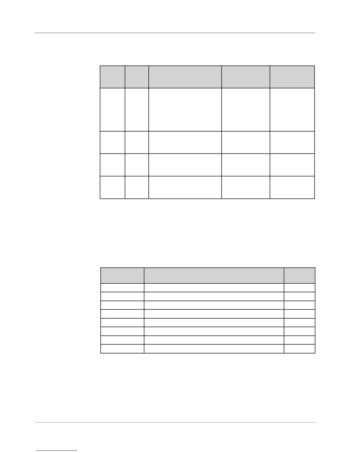
Table 4-2 Main Board LED Designations (continued)
4.3 Main
Controller
Board
Diagnostics
LED Color
When
Lit
Description Normal State Error State
CR15 Green USB connection detected LED is lit when
USB connec-
tion is detected;
blinks when USB
is active
LED stays off
after connect-
ing a USB de-
vice (indicates
a bad USB
connection)
CR25 Red Exit Sensor [DA95F only] LED lit when
sensor is
blocked
LED not lit
when sensor is
blocked
CR27 Red Feeder Sensor LED lit when
sensor is
blocked
LED not lit
when sensor is
blocked
CR28 Red Paper Sensor LED lit when
sensor is
blocked
LED not lit
when sensor is
blocked
Main Controller Board Voltage Checks
When you need to troubleshoot the Main Controller Board, measure the volt-
ages (with power applied) using a digital voltmeter at these points (see table
below).
Voltage With
Normal Range
Where It Comes From/Going Location
1.5V ±5% Generated from main board TP27
3.3V ±5% Generated from main board TP25
5V ±5% Generated from main board TP38
40V ±5% Input from power supply TP39
Ground Ground for 3.3V measurement TP26
Ground Ground for 1.5V measurement TP28
Ground Ground for 40V measurement TP40
Ground Ground for 5V measurement TP37
Table 4-3 Main Board Test Points With Voltage Ranges