DA80F/DA95F AddressRight™ Printers Service Manual (SV61962 Rev. A)
5-29
Removal and Replacement • 5
DA80F (WF81) Parts Removal
✍
TIP: If you have
replaced the lower
shaft (the shaft that
the idler rollers rest
on), you need to per-
form the idler roller
height adjustment.
7. Reinstall in reverse order.
5.16 Entry Idler
Roller Arm
(continued)
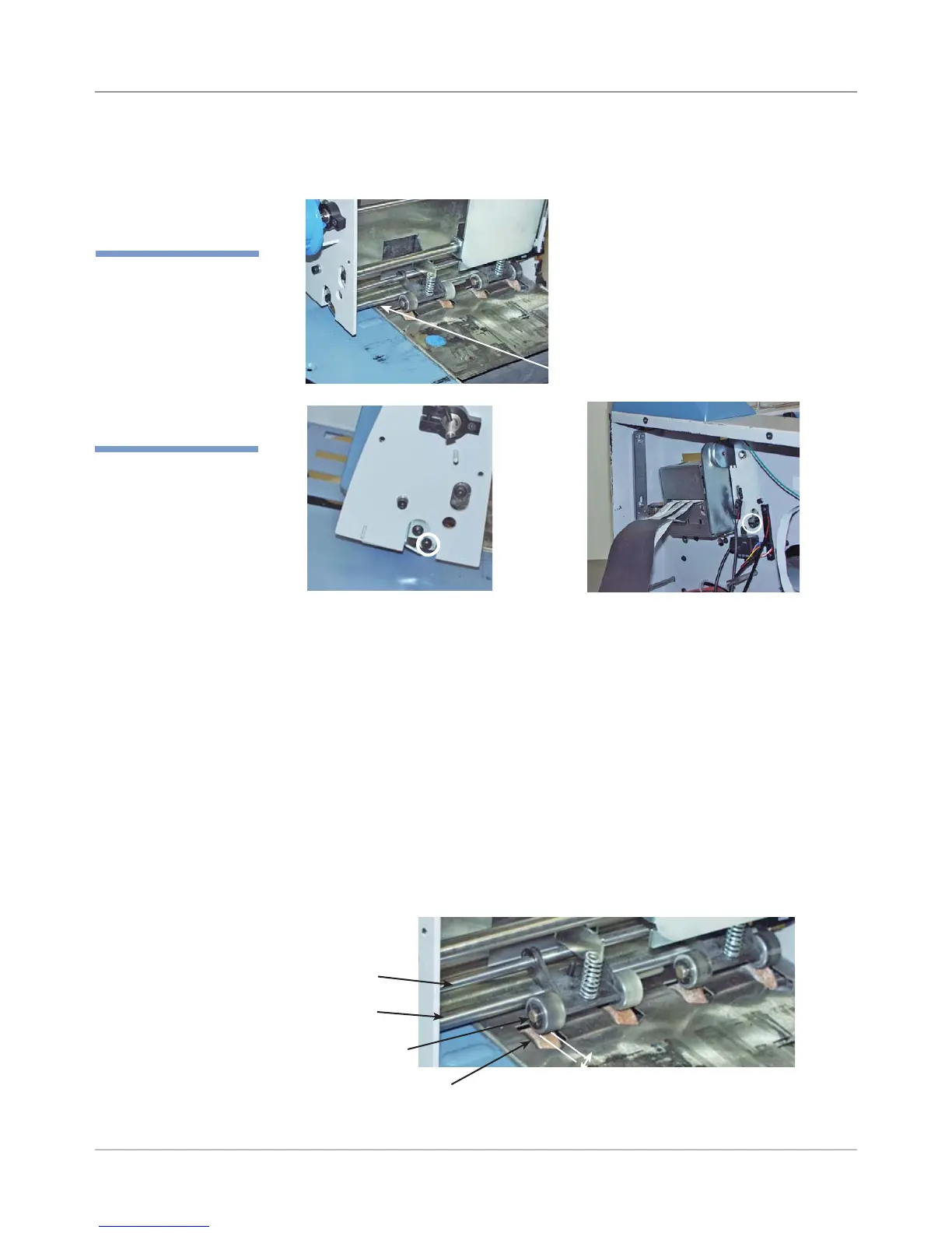
Idler Roller Height Adjustment (If Lower Shaft has Been Replaced)
Lower Shaft
Screws
for Lower
Roller
Shaft
(Circled)
6. [Only if lower shaft is to be replaced] - Unfasten screw (circled in figures be-
low) on either end of lower shaft and remove shaft. See tip note at left.
Entry idler roller height is determined by the height of the lower shaft on
which the idler rollers rest on, not the shaft on which the idler arm is at-
tached. Consequently, if the lower shaft has been replaced, you need to
verify the height of the idler rollers because they rest on it.
A. The height between the idler rollers and transport roller on deck should
be between 0.170” and 0.210”. If you don’t have a tool with the proper
gap, you can use 50 sheets of 20 lb. bond paper.
B. Adjust the lower shaft using the two screws at either end (see step 6
above) until you reach the proper height.
Height for Adjustment
(must be between
0.170” and 0.210”)
Idler Roller
Transport
Roller
Lower
Shaft
Idler Roller
Shaft