28
Installation
Before using any of the cable glands, perforate first with a screwdriver. To ensure a good seal,
the external diameter of the cables should be between 5 and 7 mm.
For information on the connections available refer to Table 1.
CAUTION
The relay outputs can only supply power in very low safety voltage (30 VAC or 42.4 VDC
maximum) and limited to 0.5 A.
The nomenclature given in the connections column of Table 1 below, refers to the same
nomenclature that is printed on the I/O board against each available connection.
When all I/O connections have been made, put the cover back on the local controller box and
secure in place with the 4 screws.
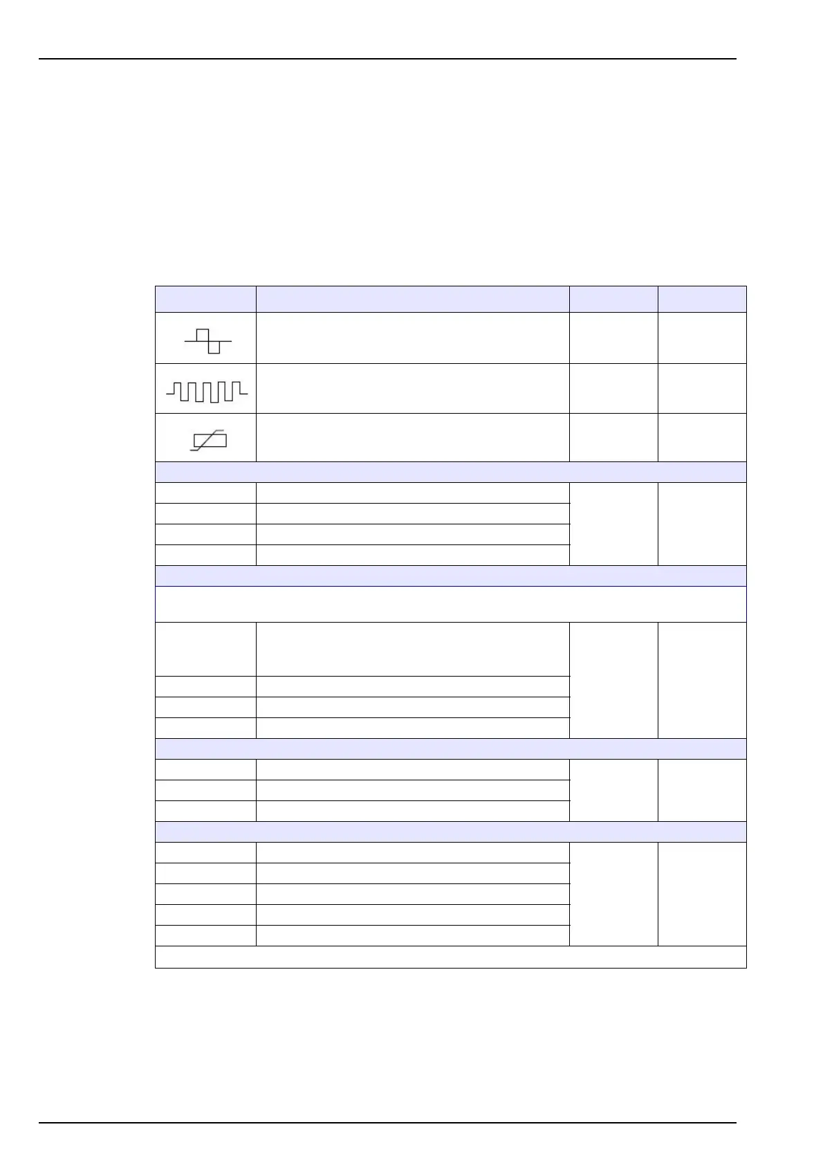
Connections Function Max. voltage Max. current
Mixer control 24 VAC 1 A
Heater control 24 VDC 1 A
Cell temperature measurement 5 VDC 1 mA
Re1 to Re6 User relay of thresholds 1 - 6
30 Veff or
42.4 VDC
0.5 A
resistive
charge
Re7 to Re10 Not used
Re11 Warning alarm
Re12 System alarm (NO and NC switches are available)
Note: Dry relays are used for all the following logical inputs. At best, provide 1 dry circuit (no voltage)
which will be closed to launch an action.
In1 to In6
By-pass sample measurement (channels 1 - 6)
For input In1, use terminals " in " and " - "
Terminals " + " and " out " are not used
5 VDC 5 mA
In7 to In10 Not used
In11 Remote acknowledgment of alarms
In12 Level sample detector
Iout1 to Iout6 Analog output 0-20 or 4-20 mA (channels 1 - 6)
24 VDC 23 mAIout7 Analyzer status
Iout8 Not used
Vout1 Sample electrovalve control
30 VDC 1 A
Vout2 to Vout7 Sample selection electrovalve controls (channels 1 - 6)
Vout8 Calibration pump
Vout9 to Vout11 Reagent pumps
Vout12 Drain pump
Table 1 Relay functions