DESCRIPTION OF PROGRAMMING PARAMETERS
Parameter /
Default Value
G4.1.5 / Multi-
function Digital
Input 1
configuration
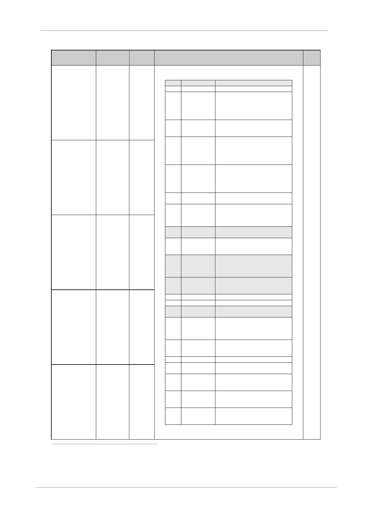
It allows user to configure the digital inputs for individual use.
‘Start’ command from a normally open
push button (NO). First, It is necessary
to configure another input as a ‘Stop’
command from a normally closed
contact (NC).
‘Stop’ command from a normally
closed push button. Stop mode is
adjusted in G7.1 STOP 1. (NC)
‘Stop’ command from a normally
closed pushbutton. Stop mode is
adjusted in G7.2 STOP 2. Activation of
the input in this mode also acts as a
‘Reset’ signal. (NC)
‘Stop’ command from a normally
closed pushbutton. Stop mode is
adjusted in G7.1 STOP 1. Activation of
the input in this mode also acts a
‘Reset’ signal. (NC)
It allows start when closed, and stop
when open (2 wires start / stop). (NO)
It allows start when closed and stop
when open (2 wires start / stop).
Activation of this input also acts a fault
reset. (NO)
‘Reset’ signal by push button. (NC).
See Note.
‘Start’ command and inch speed 1
when closed. Inch speed is
programmed in G15.1 INCH1. (NO)
‘Start’ command and inch speed 2
when closed. Inch speed is
programmed in G15.2 INCH2. (NO)
[1]
.
It causes deceleration of the motor
until motor is stopped, and inverts the
rotation direction. (NO)
[2]
.
It inverts the fixed speed reference set
in G15.1, G15.2 or G15.3. (NO)
[2]
.
It active acceleration and deceleration
ramps are enabled. Alternative
acceleration and deceleration rates are
programmed in G5.3 and G5.4. (NO)
It allows selection of the alternative
speed reference as programmed in
G3.2. (NO)
It activates the alternative control mode
as programmed in G4.1.2. (NO)
Like the option 06, but ‘Reset’ signal
will be activated after the drive is
stopped. (NO)
‘Stop’ command from a normally
closed pushbutton. Stop mode is
adjusted in G7.2 STOP 2. (NC)
It will change to the alternative speed
limits as programmed in G10.3 and
G10.4. (NO).
Note: See following page.
G4.1.6 / Multi-
function Digital
Input 2
configuration
G4.1.7 / Multi-
function Digital
Input 3
configuration
G4.1.8 / Multi-
function Digital
Input 4
configuration
G4.1.9 / Multi-
function Digital
Input 5
configuration
Note: The user can choose this option independently of the selected program (STÁNDARD or PUMP) and the used
control mode (LOCAL, REMOTE, SERIAL COMMS).
[1]
If two inputs set to options ‘08 START + INCH1’ and ‘09 START + INCH2’ are activated at the same time the
combination of ‘START + INCH3’ programmed in G15.3 INCH3 is enabled.
[2]
Rotation inversion in ‘G10.11 INVERSION ?=Y’ must be enabled.