A --- 1 0
Powerware 9330 (10 kVA--40 kVA) Installation and Operation
164201300 Rev . N 013004
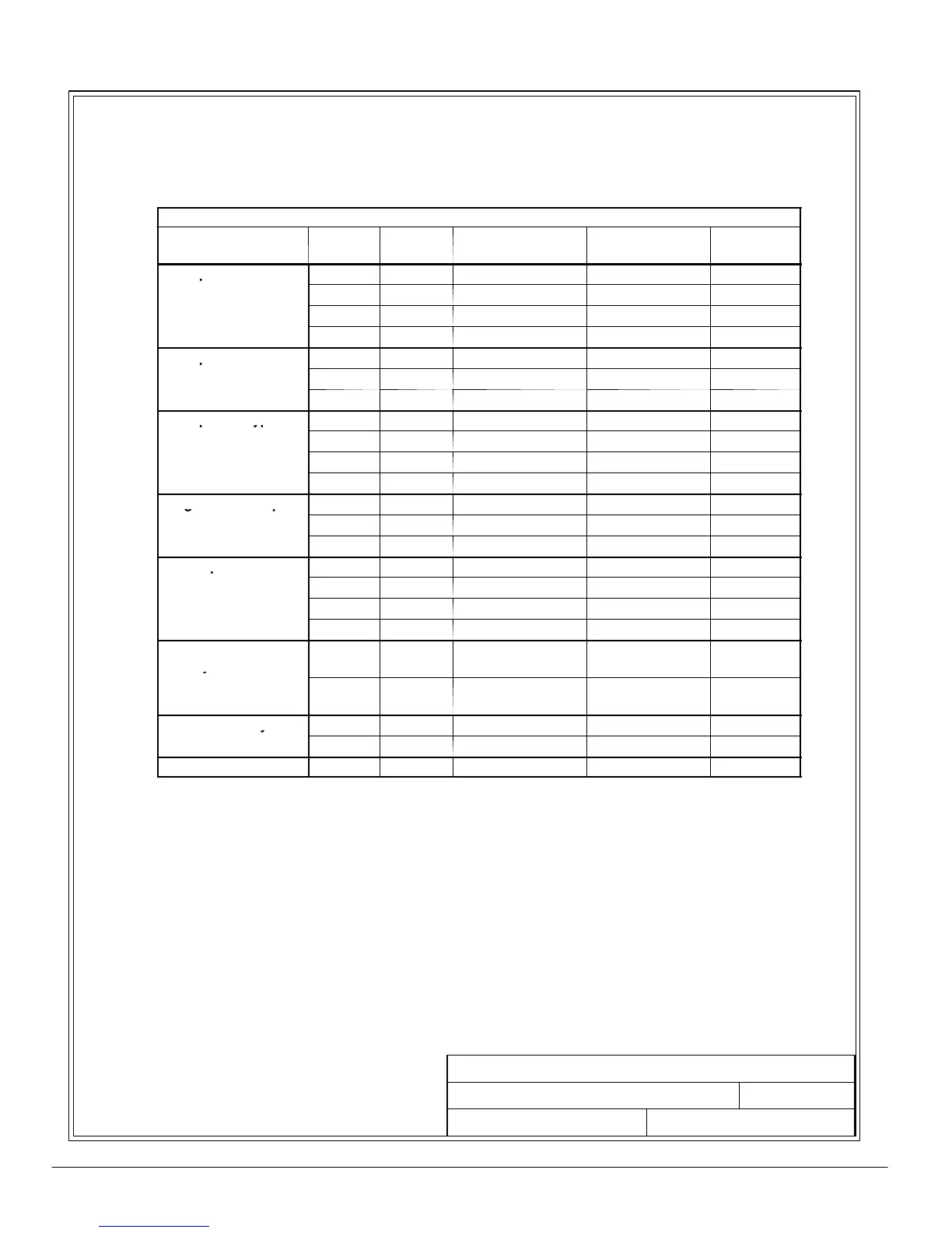
9. Terminals are UL and CSA rated at 90˚C. Refer to Tables N through Q for power cable
terminations, and Tables R through U for conduit requirements. Drawings 164201300---8
through 164201300---12 show the location of the power cable terminals inside the UPS,
Options, and Battery Cabinets.
Table N. UPS Cabinet Power Cable Terminations Powerware 9330 (10 kVA---20 kVA)
Terminal Function Te rm i na l Function
Size of Pressure
Termination
Tightening Torque
N-M (lb-in.)
Type
Screw
AC Input to UPS
E6 Phase A 1 --- # 1 4 --- 2 / 0
13.5 (120)
3/16 in. Hex
Rectifier and Bypass
E7 Phase B 1 --- # 1 4 --- 2 / 0
13.5 (120)
3/16 in. Hex
ng
e
nput
E8 Phase C 1 --- # 1 4 --- 2 / 0
13.5 (120)
3/16 in. Hex
E12 Neutral 1 --- # 8 --- 2 / 0
13.5 (120)
3/16 in. Hex
AC Input to UPS
E1 Phase A 1 --- # 1 4 --- # 3 2.5 (22) Phillips
Rectifier (CB1)
E2 Phase B 1 --- # 1 4 --- # 3 2.5 (22) Phillips
ua
nput
E3 Phase C 1 --- # 1 4 --- # 3 2.5 (22) Phillips
AC Input To Bypass
E6 Phase A 1 --- # 1 4 --- 2 / 0
13.5 (120)
3/16 in. Hex
(Dual Input)
E7 Phase B 1 --- # 1 4 --- 2 / 0
13.5 (120)
3/16 in. Hex
E8 Phase C 1 --- # 1 4 --- 2 / 0
13.5 (120)
3/16 in. Hex
E12 Neutral 1 --- # 8 --- 2 / 0
13.5 (120)
3/16 in. Hex
Single Feed Jumper
— Phase A N/A 6 (50) 1/4–20 Stud
on Bypass Input
— Phase B N/A 6 (50) 1/4–20 Stud
erm
na
oc
— Phase C N/A 6 (50) 1/4–20 Stud
AC Output to Critical
E9 Phase A 1 --- # 8 --- 2 / 0
13 (110)
3/16 in. Hex
Load
E10 Phase B 1 --- # 8 --- 2 / 0
13 (110)
3/16 in. Hex
E11 Phase C 1 --- # 8 --- 2 / 0
13 (110)
3/16 in. Hex
E12 Neutral 1 --- # 8 --- 2 / 0
13 (110)
3/16 in. Hex
DC Input from
Battery to UPS
N/A
Battery
(+)
Red Battery
Connector
N/A N/A
N/A
Battery
(---)
Black Battery
Connector
N/A N/A
External Battery
E4 Positive 1 --- # 8 --- 2 / 0
13 (110)
3/16 in. Hex
Input to UPS
E5 Negative 1 --- # 8 --- 2 / 0
13 (110)
3/16 in. Hex
Customer Ground Ground Ground 2 --- # 1 4 --- 1 / 0 5.6 (50) Slotted
DESCRIPTION:
DATE:
DRAWING NO:
9of17
SHEET:
REVI SION:
N
013004
164201300---1
POWER WIRING INSTALLATION NOTES
NOTE: Customer ground, size 1/0, can
be run in any conduit listed in
Tab le s R a n d S.