I
I
I0
I
I
I
I
I
I
IO
I
I
I
I
I
I
1.
I0
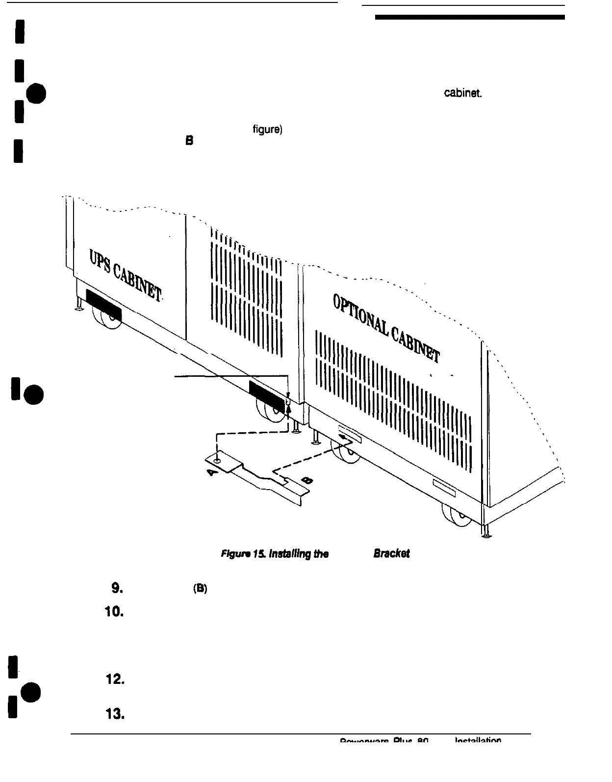
7. Remove the nut from the screw in the lower door hinge of the UPS
cabinet.
8.
Hold the angled bracket parallel to the floor (see Figure 15). The flange with the
hole in it (labeled A in the figure) should be facing upward. The flange with the
tab (labeled
B
in the figure) should be pointing toward the slot in the base of the
optional cabinet.
(see Figure 15 on page 24)
Lower-
door hinge
Ffgwe
16.
lnsfafhg
fhe
Angled
Emcket
9.
Insert the tab (B) into the slot in the base of the optional cabinet
10.
Slide the bracket toward the UPS cabinet while slipping the hole (A) onto the
screw in the lower door hinge of the UPS cabinet
11.
Replace the nut (removed in step 7 on page 24) on the hinge screw to secure
the angled bracket in place.
12.
Repeat steps 2 through 11 to join another optional cabinet to the other side of
the UPS cabinet.
13.
Attach a ground bus to the joined cabinets using the procedure on page 26.