I.
I
I
0
I
I
I
I
I
I
IO
I
!
I
I
I
I
I
I0
To prepare the input transformer cabinet for wiring to the UPS:
1.
Roll the UPS into its final operating position and secure it with
its
leveling feet.
2. Roll the input transformer cabinet to the left of the UPS. Join the two cabinets
using the appropriate method described in “Joining Cabinets” on page
11.
3. Open the door of the input transfoner cabinet (press the top of the door latch,
twist the latch lever clockwise 66’, and pull the door outward).
4. Remove the top and bottom deadfronts. Set the deadfronts and screws aside
for remounting later.
5.
Secure the transformer cabinet to the UPS cabinet at the points shown in Figure
24 on page 41.
(See “Joining an Optional Cabinet to the UPS” on page 22.)
6.
Attach a ground bus between the UPS and transformer cabinet frames, using
the procedure on page 26.
7. Securethe cabinet wfth its leveling feet.
To wire the
input
transformer cabinet to the UPS:
1.
Cables for interconnecting the input transformer to the UPS are coiled and
tie-wrapped in place inside the input transformer cabinet Locate and uncoil
the cables. The connections inside the transformer cabinet are already made
(see Figure 24 on page 41). Each cable is marked with
its
designation point in
the UPS cabinet.
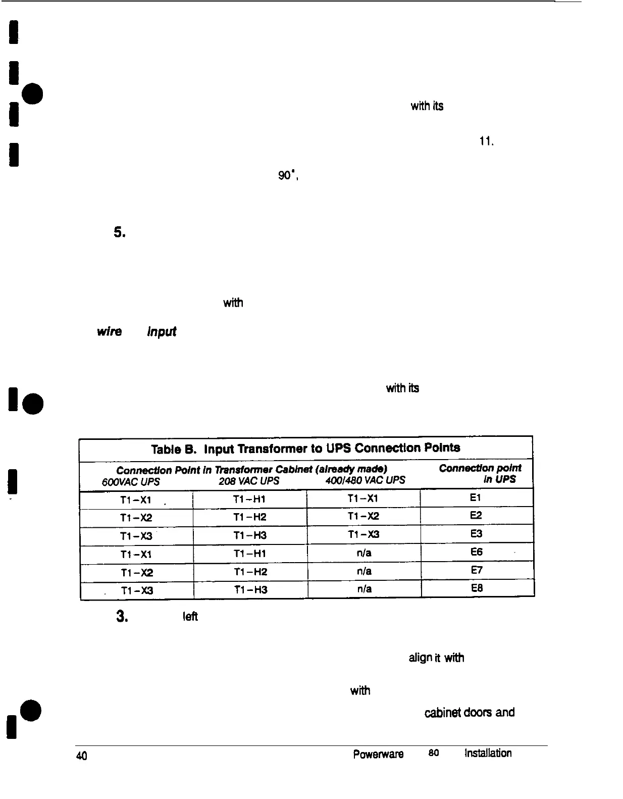
2. Connect the cables according to input vottage as shown in in Table 6:
3.
Mount the
I&
side cover to the left side of the transformer cabinet
a. Mount the hanger bracket to the top left side of the transformer cabinet.
b.
Hang the left side cover on the hanger bracket and align
ft
wfth the front
and rear of the transformer cabinet
C. Secure the left side cover at the bottom with screws.
4.
Replace the deadfront on the UPS cabinet. Close the
UPS
cabinet
do0t-s
ad
the input transformer cabinet door.
40
p~~erwara Plus
SC
UPS
lnstallatfon
Manual