b
0
B
0
L
I
k
f
t
t
P
u
The
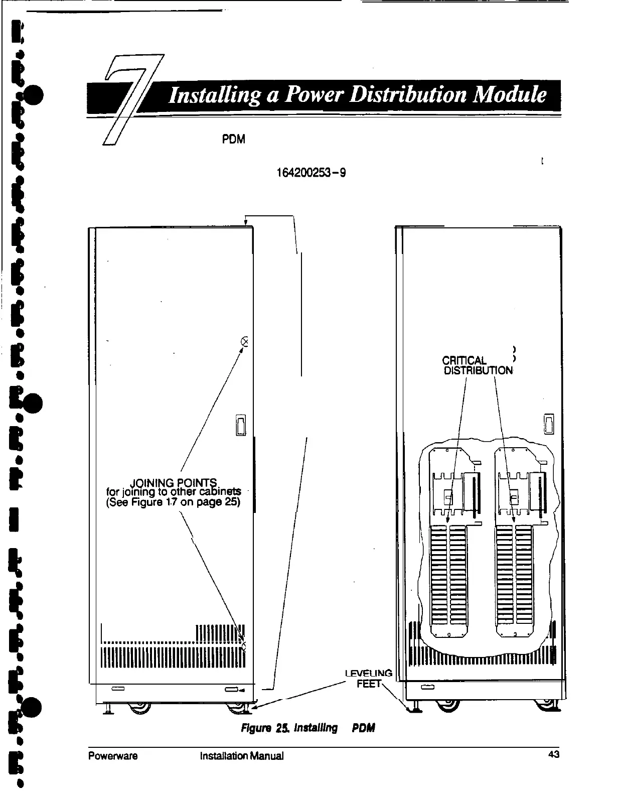
PDM
cabinet has two interface panels, each containing 42 poles
for breaker switches you can assign with flexibility to meet the needs of your
facility. Each panel is controlledby one 225 amp feeder breaker. The PDM cabinet
arrives as shown in Drawing 1942W253-9 on page A-19 and Figure 25, below.
Before installing the PDM, be sure you have prepared the UPS according to the
instructions on page 19.
\
1
111111111111111111111111111111111111,.
llllllllllllllllllllllllllllllllllllfi
=I
--
JOINING POINTS
for joining to UPS
(See Figure 14
on page 23)
AC OUTPUT TO
CRrnCAL
LOAD
DlSTFtlBUTfON
Ffgum
25.
h9taM7g
a
POW
Cabinet
Powenvars
Plus so UPS lnstallaticn Manual