I
I
I0
I
I
I
I
I
I
Ia
I
I
I
I
I
I
I
To prepare the PDM
cabinet
for
wlrlng
to the UPS:
1.
Roll the UPS into its final operating position and secure it with its leveling feet.
2. Roll the PDM cabinet to the left of the UPS. Join the two cabinets using the
appropriate method described in “Joining Cabinets” on page 11.
3.
Open the door of the
PDM
cabinet. Remove the top and bottom deadfronts.
Set the deadfronts and screws aside for remounting later.
4. Use three bolts and three nuts from the hardware joining
kti
to secure the front
of the transformer cabinet to the front of the UPS cabinet at the points shown in
Figure 25 on page
43.
(See ‘Joining an Optional Cabinet to the UPS” on page
22.)
5.
Attach a ground bus between the frames of the UPS and PDM cabinet, using
the procedure on page 26.
6.
Secure the PDM cabinet with its front leveling feet
To wfre the
PDM
cabinet to the UPS:
1.
Cables for interconnecting the
PDM
to the UPS are coiled and tie-wrapped in
place inside the PDM cabinet The connections inside the transformer cabinet
are already made. Locate the coil of cables inside the PDM cabinet.
2. Cut the tie-wraps around
me
cables, and uncoil the cables. Each cable is
marked with its designation point in the UPS cabinet.
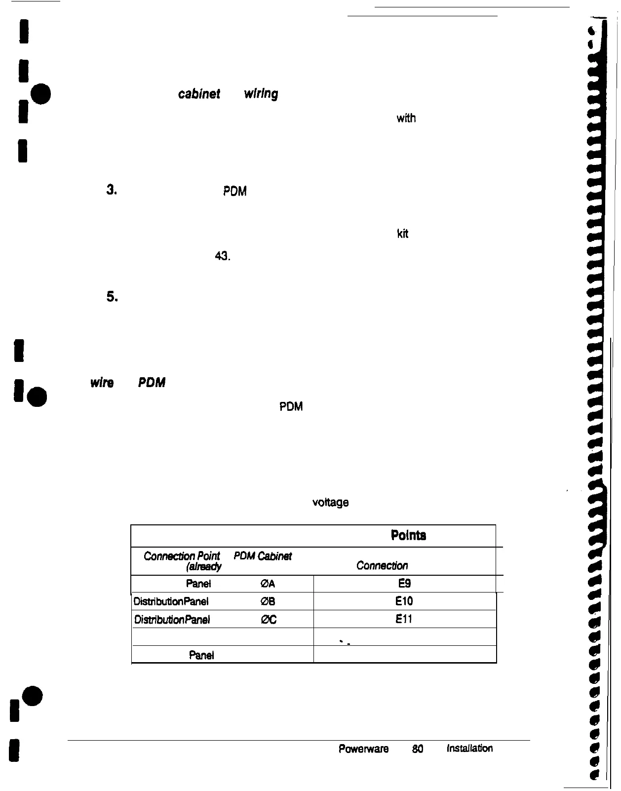
3. Connect the cables according to input
voltage
as shown in in Table C:
Table C. PDM to UPS Connection Pointe
Ccnnec2ion
Point
in
PDM
Cabinet
(sllreecly made)
Conneciion point in UPS
Distribution
Panet
(2 cables)
0A
E9
Disttibukn
Panel
(2 cables)
06
El0
Di.stribukn
panel
(2 cables) 0C
Eli
Distribution Panel (2 cables) N
-_
El2
Distribution
Panel
(2 cables) G Customer ground
44
Powerware
Plus
60
UPS
installation
Manual