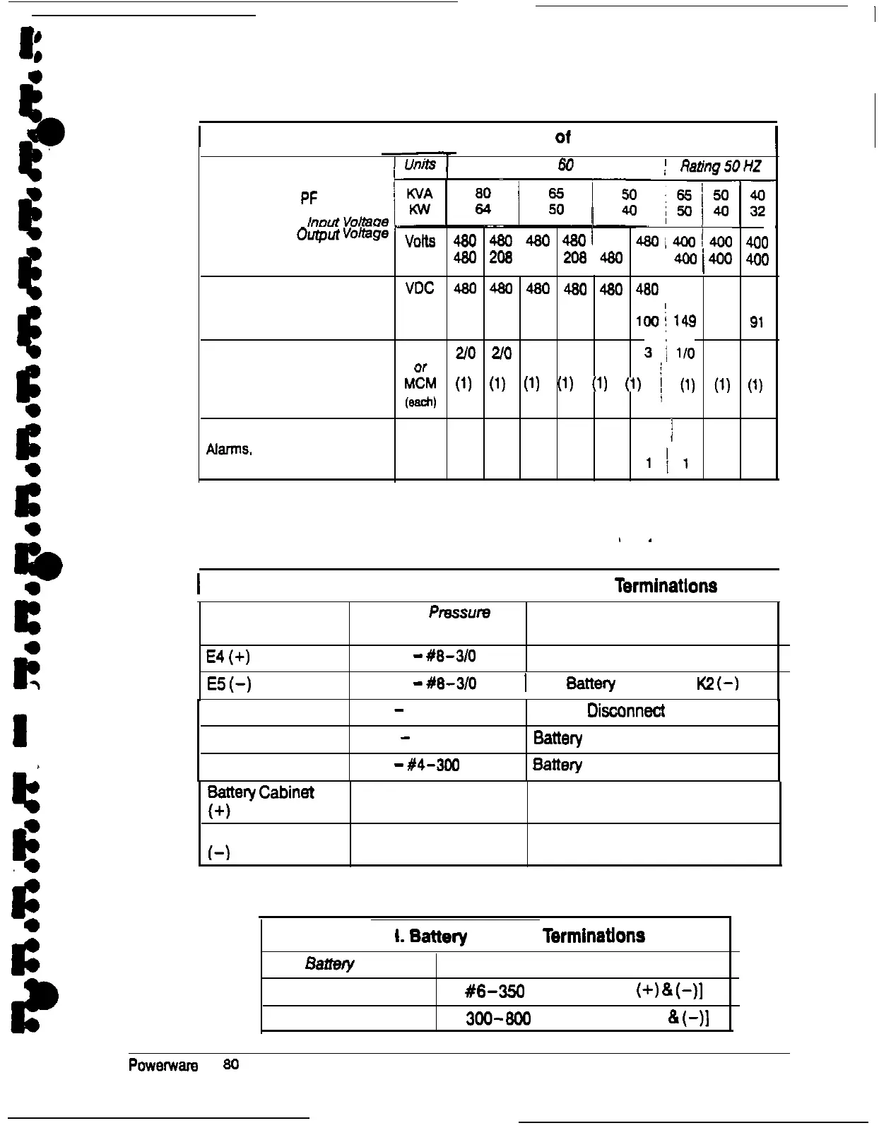
Table G. Minimum AWG Wire Size
of
External Wiring
Basic Unit Rating
at 0.8 Lagging PF Load
Rating
60
HZ
;
Rating5OHZ
‘npuivOltage
r
Output
“Ohge
VOitS
480 480
i
480 480 480 48oi4OO14OO 900
volts 480 208 480 208
I
480
208 j
400
/
400 400
DC Input from
VDC 480 480 480 480 490 480
420 420:
420
Battery to UPS(1) Positive, (1) Negative Amps
160 160 130 130 100
100; 149
114
91
Minimum Conductor AWG
2/O 2/O
1 1
3
3/l/O
2
3
Size and Number
Per Phase
ML4
(1)
(1)
(1)
(1)
(1)
(1)
j
(1)
(1)
(1)
(each)
Control Wiring to Building VAC 24 24 24 24 24
24
j
24 24
24
Alarms. Remote Monitor.
I
and Remote EPO Amps
1
1 1
1
1
111
1
1
,
.
I
Table H. Remote Battery Disconnect Power Terminations
I
Terminal
E4
(+I
E5
(-)
Size of
Pres.sufw
Termination
1
-
#8-3/O
1
-
#S-3/0
Terminal Function
UPS Battery Contactor K2 (+)
1
UPS
Battery
Contactor
KZ
(-)
Breaker (+)
Breaker (-)
Breaker (jumper)
1
-
#4-300 MCM
Battery
Disoonnect
(+)
1
-
#4-300 MCM
Ballery
Disconnect (-)
1
-
#4-3Gil
MCM
Battery
Disconnect
(jumper)
F
Cabinet
+
See Table NO TAG
Stand-alone battery cabinet (+)
Battery Cabinet
t-1
See Table NO TAG
Stand- alone battery cabinet (-)
Table
I.
Battery
Cabinet
Terminations
Bat&y
Pack
Size of Pressure Termination
Type 1 Battery Cabinet
(1)
#6-350
MCM [Breaker
(+)
8
(-)I
Type 2 Battery Cabinet
(1) 300~800 MCM [Breaker (+)
8
(-)I
l
C
Powerware Plus 80 UPS
Installation Manual
51
l