LLC
in
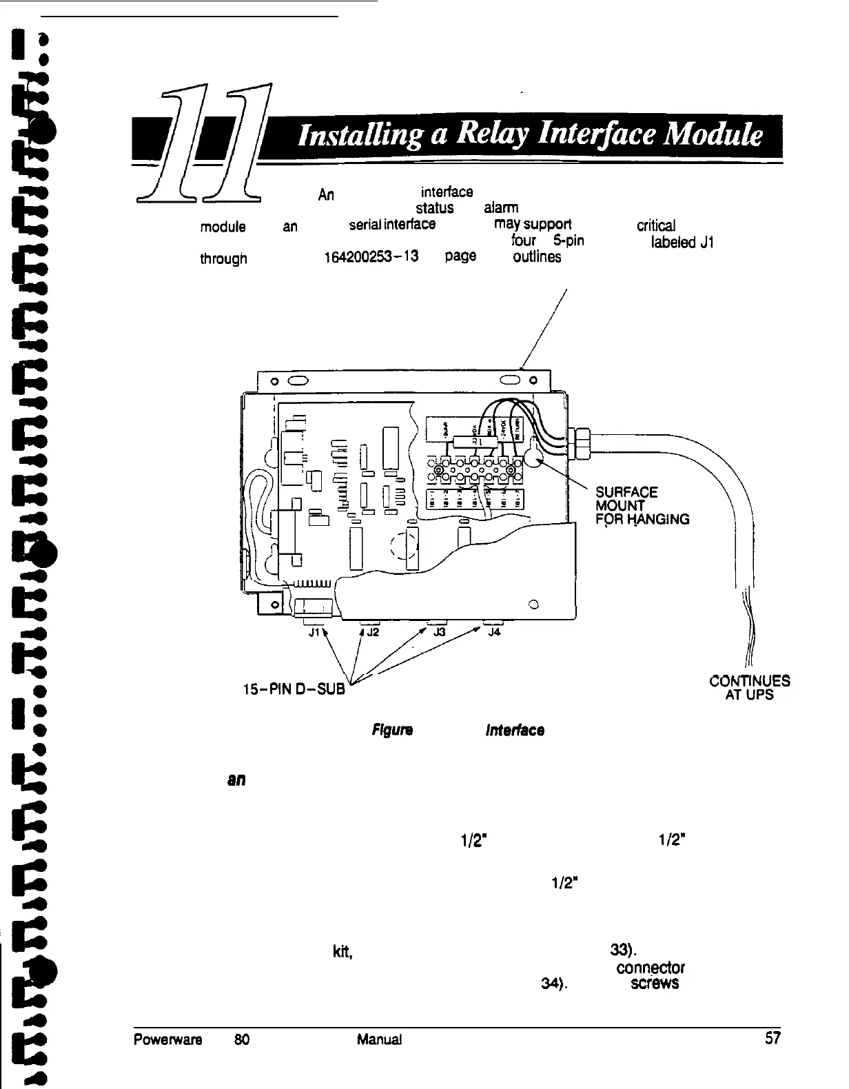
optional relay
interface
module uses relay contact closures to
indicate the operating
status
and
alam
condition of the UPS system. The
mccuts uses
an
RS422
serial
interfsce
line and
may
Support
Up
to eight
criticsl
loads.
Figure 32
shows the relay interface module, with its fOUr 1
s-pin
connectors
Ikbeled
Ji
through
J4.
Drawing le42002%-13 On
Ps9e
A-23
Outlines
the enclosure dimensions,
/
FLUSH MOUNT
Relay Interface Module
1%PIN
D-SUS-
CONNECTORS
Figure
32. Relay interlace Module
To install
an
RIM:
1. Securely
mount the RIM.
2. Install wiring from the RIM through
l/2”
conduit and through the
l/2”
knockout
in either the top or the bottom of the UPS cabinet.
The top entry connection requires installation of
l/2”
flexible conduit within the
UPS. Bottom entry connection requires no additional routing of conduit within
the UPS.
3. In the hardware
kit,
locate the terminal block (see Figure
Xi).
Plug the
connector on the back of the terminal block into the DE-9 conrrector on the
Communications Panel of the UPS (see Figure 34). Use two screws from the
hardware kii to secure the terminal block plate to the Communications Panel.
Powemsrs Plus
80
UPS Installation
Manual
57