EasyManuals Logo
Home>Radwin>Radio>5000

Radwin 5000 Installation Guide

Radwin 5000
139 pages
To Next Page IconTo Next Page
To Previous Page IconTo Previous Page
Page #91 background imageLoading...
Page #91 background image
RADWIN 5000 Installaon Guide
August 2023
91
Appendix A. Wiring Specicaons
A.1 Scope of this Appendix
This appendix shows wiring specicaons for the HBS and SU.
A.2 Radio unit‐PoE Cable (HBS and SU)
The radio unit‐PoE cable is shielded/outdoor class CAT‐5e, 4 twisted‐pair 24 AWG terminated with RJ‐45
connectors on both ends. A cable gland on the radio unit side provides hermec sealing.
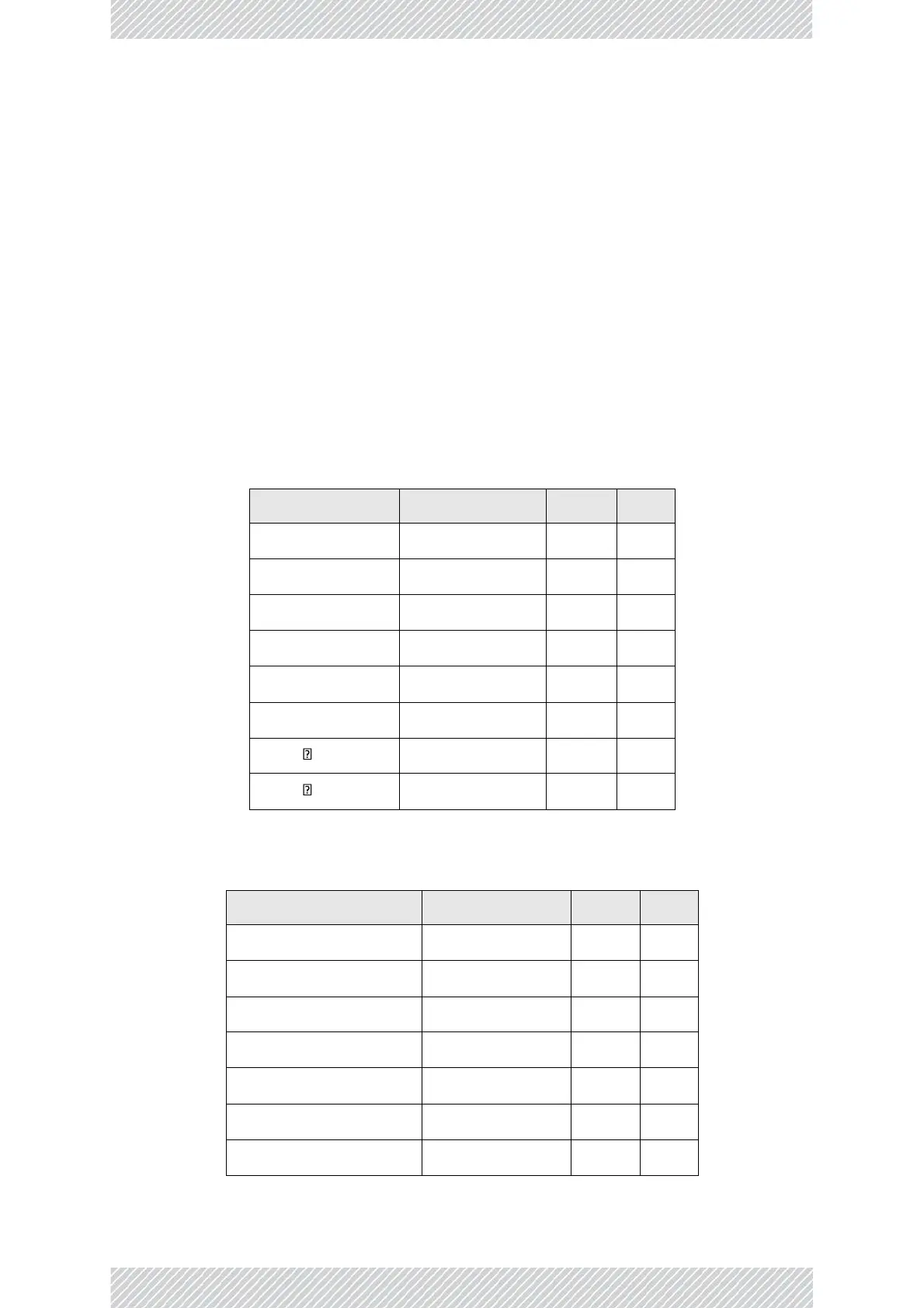
The following table shows the connector pinout:
Table 4: Radio unit‐PoE RJ‐45 Connector Pinout
Funcon
Color
PoE
ODU
Rx N
White/Green
1
1
Rx T
Green
2
2
Tx T
White/Orange
3
3
Tx N
Orange
6
6
Power (+)
Blue
4
4
Power (+)
White/Blue
5
5
Power ( )
White/Brown
7
7
Power ( )
Brown
8
8
Table 5: LAN‐GbE PoE RJ‐45 Connector Pinout
Funcon
Color
PoE
LAN
TxRx A
White/Green
1
1
TxRx A
Green
2
2
TxRx B
White/Orange
3
3
TxRx B
Orange
6
6
TxRx C & Power(+)
Blue
4
4
TxRx C & Power(+)
White/Blue
5
5
TxRx D & Power(‐)
White/Brown
7
7

Table of Contents

Other manuals for Radwin 5000

Questions and Answers:

Question and Answer IconNeed help?

Do you have a question about the Radwin 5000 and is the answer not in the manual?

Radwin 5000 Specifications

General IconGeneral
BrandRadwin
Model5000
CategoryRadio
LanguageEnglish

Related product manuals