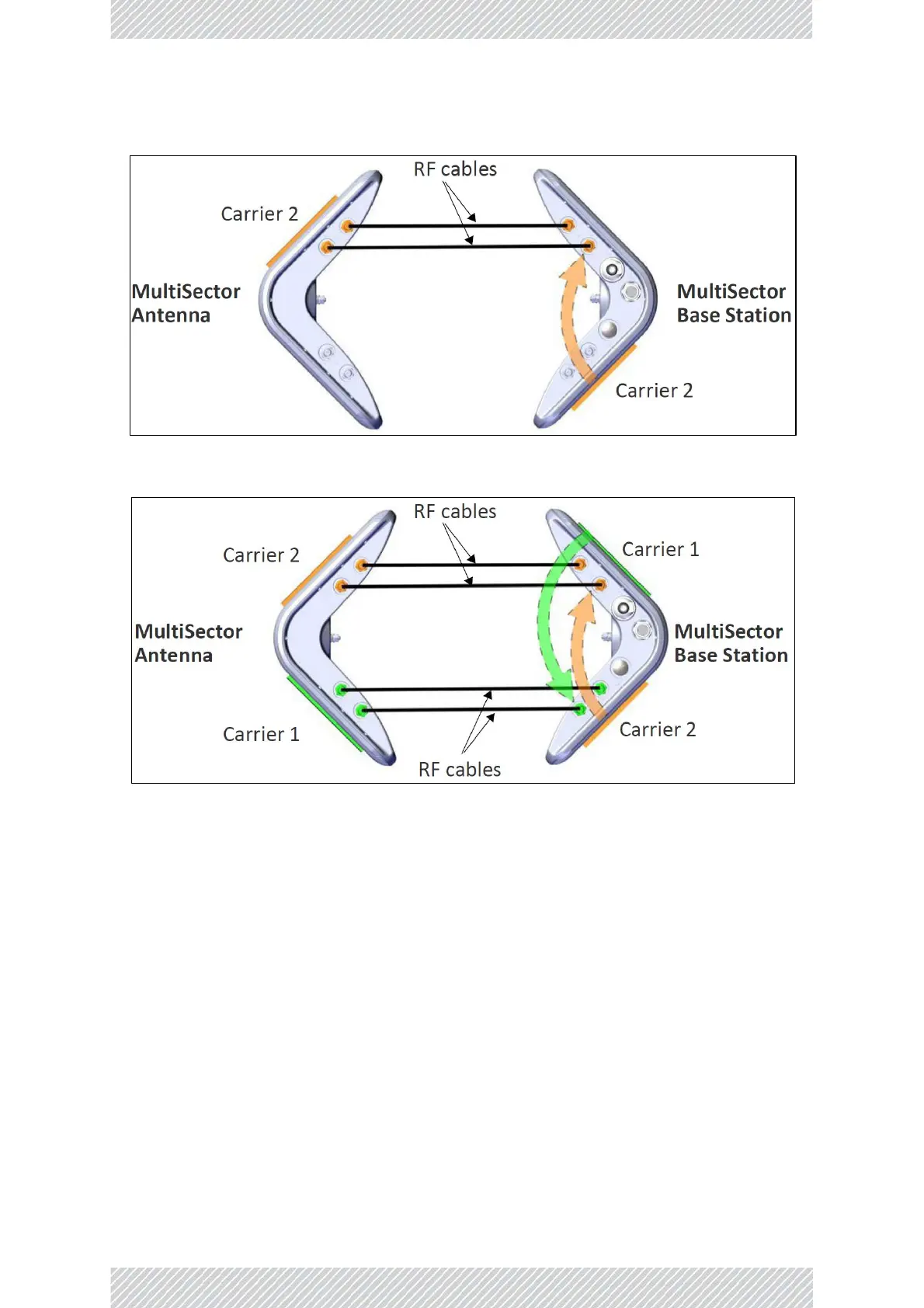
Figure 82: MulSector Base Staon Integrated connected to MulSector antenna (Carrier 2 only)
Figure 83: MulSector Base Staon Integrated connected to MulSector antenna (both Carriers)
2.13.4 Connecting MultiSector Connectorized Units to Antennas
Connect the external antennas to the radio unit as shown in Figure 84: Antenna connecon scheme for the
MulSector Connectorized unit.
• Each antenna sector has one antenna.
• Each carrier frequency is applied to two antenna sectors.
• Antenna Sector 1 uses Antenna 1V+1H, Antenna Sector 2 uses 2V+2H, Antenna Sector 3 uses Antenna
3V+3H, and Antenna Sector 4 uses 4V+4H.
• If the antenna does not have a connecon labeled “V” or “H”, but rather with a number or other leer,
make sure you stay consistent with the polarizaon. For instance, if you connect the V port on the
MulSector to the port labeled 1, make sure you do that for all the connecons.