RL78/G13 CHAPTER 29 ELECTRICAL SPECIFICATIONS
R01UH0146EJ0100 Rev.1.00 1005
Sep 22, 2011
Caution The pins mounted depend on the product. Refer to 2.1.1 20-pin products to 2.1.14 128-pin products,
and 2.1.15 Pins for each product (pins other than port pins).
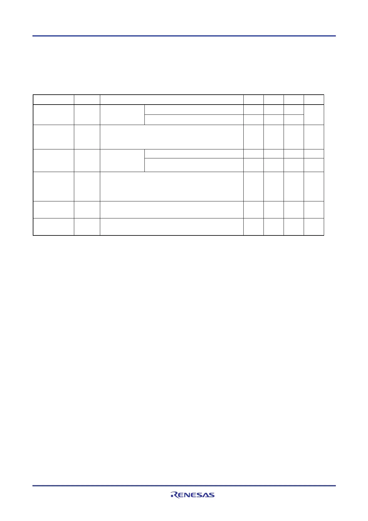
(4) Common to RL78/G13 all products
(T
A = −40 to +85°C, 1.6 V ≤ EVDD0 = EVDD1 ≤ VDD ≤ 5.5 V, VSS = EVSS0 = EVSS1 = 0 V)
Parameter Symbol Conditions MIN. TYP. MAX. Unit
Real-time clock operation 0.02
RTC operating
current
I
RTC
Notes 1, 2
fSUB = 32.768 kHz
Interval timer operation 0.02
μ
A
Watchdog timer
operating
current
I
WDT
Notes 2, 3
fIL = 15 kHz 0.22
μ
A
Normal mode, AVREFP = VDD = 5.0 V 1.3 1.7 mA A/D converter
operating
current
IADC
Note 4
When conversion
at maximum
speed
Low voltage mode, AV
REFP = VDD = 3.0 V 0.5 0.7 mA
Temperature
sensor
operating
current
ITMPS 75
μ
A
LVD operating
current
I
LVI
Note 5
0.08
μ
A
BGO operating
current
I
BGO
Note 6
2.50 12.20
mA
Notes 1. Current flowing only to the real-time clock (excluding the operating current of the XT1 oscillator). The TYP.
value of the current value of the RL78/G13 is the sum of the TYP. values of either IDD1 or IDD2, and IRTC, when
the real-time clock operates in operation mode or HALT mode. The I
DD1 and IDD2 MAX. values also include the
real-time clock operating current. However, I
DD2 subsystem clock operation includes the operational current of
the real-time clock.
2. When high speed on-chip oscillator and high-speed system clock are stopped.
3. Current flowing only to the watchdog timer (including the operating current of the low-speed on-chip oscillator).
The current value of the RL78/G13 is the sum of I
DD1, IDD2 or IDD3 and IWDT when fCLK = fSUB when the watchdog
timer operates in STOP mode.
4. Current flowing only to the A/D converter. The current value of the RL78/G13 is the sum of I
DD1 or IDD2 and IADC
when the A/D converter operates in an operation mode or the HALT mode.
5. Current flowing only to the LVD circuit. The current value of the RL78/G13 is the sum of I
DD1, IDD2 or IDD3 and
I
LVI when the LVD circuit operates in the Operating, HALT or STOP mode.
6. Current flowing only to the BGO. The current value of the RL78/G13 is the sum of IDD1 or IDD2 and IBGO when
the BGO operates in an operation mode.
Remarks 1. f
IL: Low-speed on-chip oscillator clock frequency
2. f
SUB: Subsystem clock frequency (XT1 clock oscillation frequency)
3. f
CLK: CPU/peripheral hardware clock frequency
4. Temperature condition of the TYP. value is TA = 25°C
<R>

 Loading...


