RL78/G13 CHAPTER 9 CLOCK OUTPUT/BUZZER OUTPUT CONTROLLER
R01UH0146EJ0100 Rev.1.00 466
Sep 22, 2011
(2) Port mode register 1, 3, 5, 14 (PM1, PM3, PM5, PM14)
These registers set input/output of port in 1-bit units.
For example in 64-pin products, when using the P140/INTP6/PCLBUZ0 and P141/INTP7/PCLBUZ1 pins for clock
output and buzzer output clear PM140 and PM141 bits and the output latches of P140 and P141 to 0.
The PM1, PM3, PM5, PM14 registers can be set by a 1-bit or 8-bit memory manipulation instruction.
Reset signal generation sets these registers to FFH.
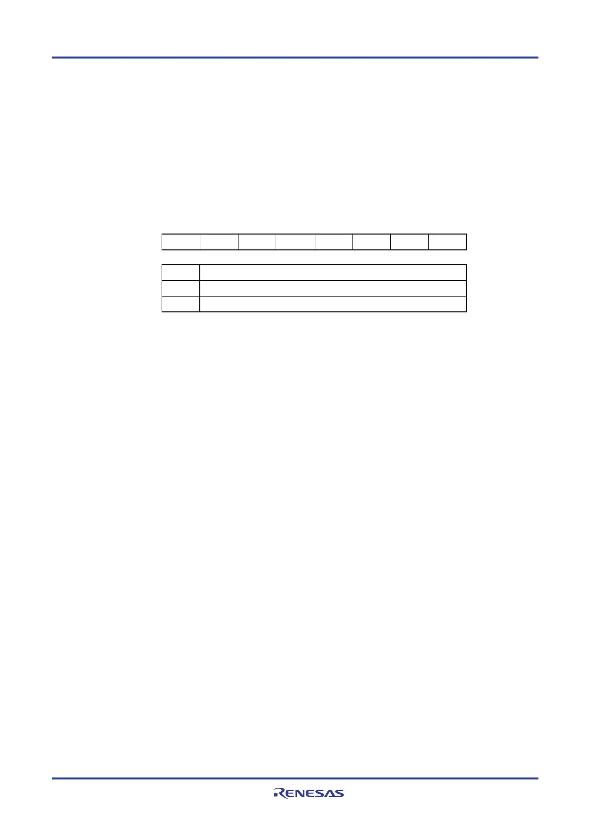
Figure 9-3. Format of Port Mode Register 14 (PM14) (64-pin products)
Address: FFF2EH After reset: FFH R/W
Symbol 7 6 5 4 3 2 1 0
PM14 PM147 PM146 1 1 1 1 PM141 PM140
PMmn Pmn pin I/O mode selection (mn = 140, 141, 146, 147)
0 Output mode (output buffer on)
1 Input mode (output buffer off)
Remark For details of the port mode register other than 64-pin products, see 4. 3 Registers Controlling Port
Function.
<R>

 Loading...


