RL78/G13 CHAPTER 9 CLOCK OUTPUT/BUZZER OUTPUT CONTROLLER
R01UH0146EJ0100 Rev.1.00 465
Sep 22, 2011
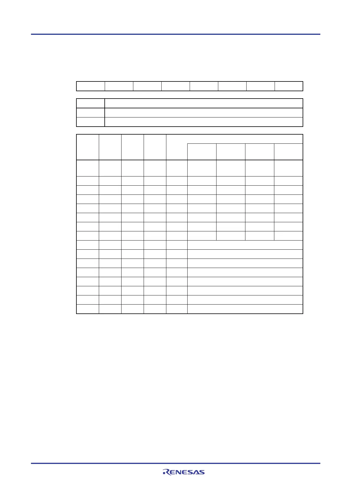
Figure 9-2. Format of Clock Output Select Register n (CKSn)
Address: FFFA5H (CKS0), FFFA6H (CKS1) After reset: 00H R/W
Symbol <7> 6 5 4 3 2 1 0
CKSn PCLOEn 0 0 0 CSELn CCSn2 CCSn1 CCSn0
PCLOEn PCLBUZn pin output enable/disable specification
0 Output disable (default)
1 Output enable
PCLBUZn pin output clock selection CSELn CCSn2 CCSn1 CCSn0
f
MAIN =
5 MHz
fMAIN =
10 MHz
fMAIN =
20 MHz
fMAIN =
32 MHz
0 0 0 0 fMAIN 5 MHz 10 MHz
Note
Setting
prohibited
Note
Setting
prohibited
Note
0 0 0 1 fMAIN/2 2.5 MHz 5 MHz 10 MHz
Note
16 MHz
Note
0 0 1 0 fMAIN/2
2
1.25 MHz 2.5 MHz 5 MHz 8 MHz
Note
0 0 1 1 fMAIN/2
3
625 kHz 1.25 MHz 2.5 MHz 4 MHz
0 1 0 0 fMAIN/2
4
312.5 kHz 625 kHz 1.25 MHz 2 MHz
0 1 0 1 fMAIN/2
11
2.44 kHz 4.88 kHz 9.76 kHz 15.63 kHz
0 1 1 0 fMAIN/2
12
1.22 kHz 2.44 kHz 4.88 kHz 7.81 kHz
0 1 1 1 fMAIN/2
13
610 Hz 1.22 kHz 2.44 kHz 3.91 kHz
1 0 0 0 fSUB 32.768 kHz
1 0 0 1 fSUB/2 16.384 kHz
1 0 1 0 fSUB/2
2
8.192 kHz
1 0 1 1 fSUB/2
3
4.096 kHz
1 1 0 0 fSUB/2
4
2.048 kHz
1 1 0 1 fSUB/2
5
1.024 kHz
1 1 1 0 fSUB/2
6
512 Hz
1 1 1 1 fSUB/2
7
256 Hz
Note Use the output clock within a range of 16 MHz. Furthermore, when using the output clock at 2.7 V ≤ V
DD < 4.0
V, can be use it within 8 MHz only. See 29.5 AC Characteristics for details.
Cautions 1. Change the output clock after disabling clock output (PCLOEn = 0).
2. To shift to STOP mode when the main system clock is selected (CSELn = 0), set PCLOEn = 0
before executing the STOP instruction. When the subsystem clock is selected (CSELn = 1),
PCLOEn = 1 can be set because the clock can be output in STOP mode.
3. In the low-consumption RTC mode (when the RTCLPC bit of the operation speed mode control
register (OSMC) = 1), it is not possible to output the subsystem clock (f
SUB) from the PCLBUZn
pin.
Remarks 1. n = 0, 1
2. f
MAIN: Main system clock frequency
f
SUB: Subsystem clock frequency
<R>

 Loading...


