RL78/G13 CHAPTER 11 A/D CONVERTER
R01UH0146EJ0100 Rev.1.00 501
Sep 22, 2011
(12) Port mode control registers 0, 3, 10, 11, 12, 14 (PMC0, PMC3, PMC10, PMC11, PMC12, PMC14)
This register switches the ANI16 to ANI26 pins to digital I/O of port or analog input of A/D converter.
These registers can be set by a 1-bit or 8-bit memory manipulation instruction.
Reset signal generation clears these registers to FFH.
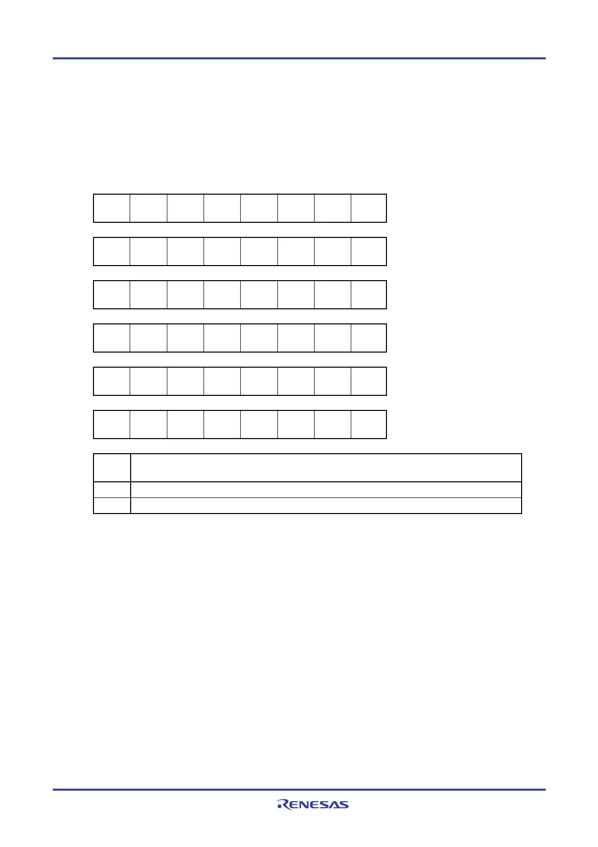
Figure 11-16. Format of Port Mode Control Register
Symbol 7 6 5 4 3 2 1 0 Address After reset R/W
PMC0 1 1 1 1
PMC03
Note 2
PMC02
Note 2
PMC01
Note 1
PMC00
Note 1
F0060H FFH R/W
PMC3
PMC37
Note 3
PMC36
Note 3
PMC35
Note 3
1 1 1 1 1 F0063H FFH R/W
PMC10 1 1 1 1 1 1 1
PMC100
Note 4
F006AH FFH R/W
PMC11
PMC117
Note 3
PMC116
Note 3
PMC115
Note 3
1 1 1 1 1 F006BH FFH R/W
PMC12 1 1 1 1 1 1 1
PMC120
Note 5
F006CH FFH R/W
PMC14
PMC147
Note 6
1 1 1 1 1 1 1 F006EH FFH R/W
PMCmn
Pmn pin digital I/O/analog input selection
(m = 0, 3, 10 to 12, 14; n = 0 to 3, 5 to 7)
0 Digital I/O (alternate function other than analog input)
1 Analog input
Notes 1. 20-, 24-, 25-, 30-, 32-pin products only
2. 52-, 64-, 80-, 100-, 128-pin products only
3. 128-pin products only
4. 80-, 100-, 128-pin products only
5. 30-, 32-, 36-, 40-, 44-, 48-, 52-, 64-, 80-, 100-, 128-pin products only
6. All products
<R>

 Loading...


