RL78/G13 CHAPTER 11 A/D CONVERTER
R01UH0146EJ0100 Rev.1.00 502
Sep 22, 2011
(13) Port mode register 0, 2, 3, 10, 11, 12, 14, 15 (PM0, PM2, PM3, PM10, PM11, PM12, PM14, PM15)
When using the ANI0 to ANI14 or ANI16 to ANI26 pin for an analog input port, set the PMmn bit to 1. The output
latches of Pnm at this time may be 0 or 1.
If the PMmn bits are set to 0, they cannot be used as analog input port pins.
The PMmn registers can be set by a 1-bit or 8-bit memory manipulation instruction.
Reset signal generation sets these registers to FFH.
Caution If a pin is set as an analog input port, not the pin level but “0” is always read.
Remark m = 0, 2, 3, 10, 11, 12, 14, 15, n = 0 to 7
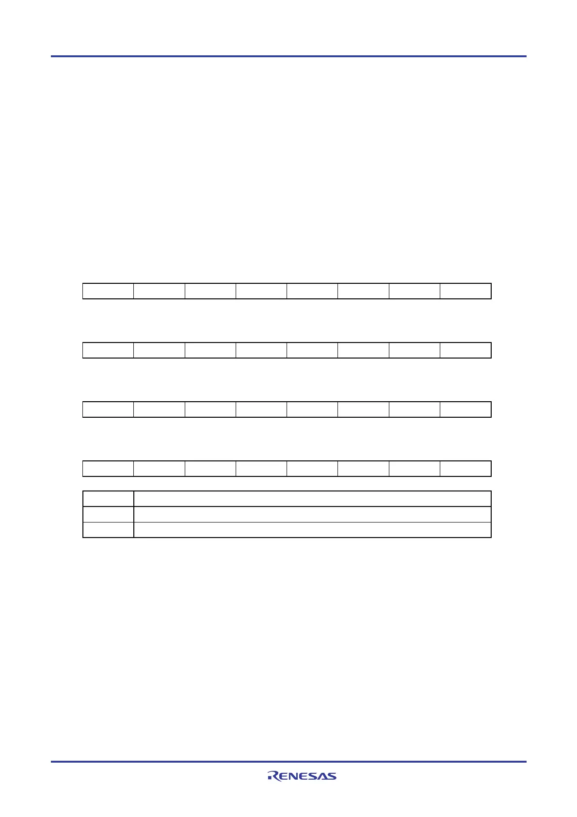
Figure 11-17. Formats of Port Mode Registers 0, 2, 12, and 14 (PM0, PM2, PM12, PM14) (64-pin products)
Address: FFF20H After reset: FFH R/W
Symbol 7 6 5 4 3 2 1 0
PM0 PM07 PM06 PM05 PM04 PM03 PM02 PM01 PM00
Address: FFF22H After reset: FFH R/W
Symbol 7 6 5 4 3 2 1 0
PM2 PM27 PM26 PM25 PM24 PM23 PM22 PM21 PM20
Address: FFF2CH After reset: FFH R/W
Symbol 7 6 5 4 3 2 1 0
PM12 1 1 1 1 1 1 1 PM120
Address: FFF2EH After reset: FFH R/W
Symbol 7 6 5 4 3 2 1 0
PM14 1 1 1 1 1 1 PM141 PM140
PMmn Pmn pin I/O mode selection (mn = 00 to 07, 20 to 27, 120, 140, 141)
0 Output mode (output buffer on)
1 Input mode (output buffer off)
Remark For details of the port mode register other than 64-pin products, see 4. 3 Registers Controlling Port
Function.
<R>

 Loading...


