RL78/G13 CHAPTER 11 A/D CONVERTER
R01UH0146EJ0100 Rev.1.00 503
Sep 22, 2011
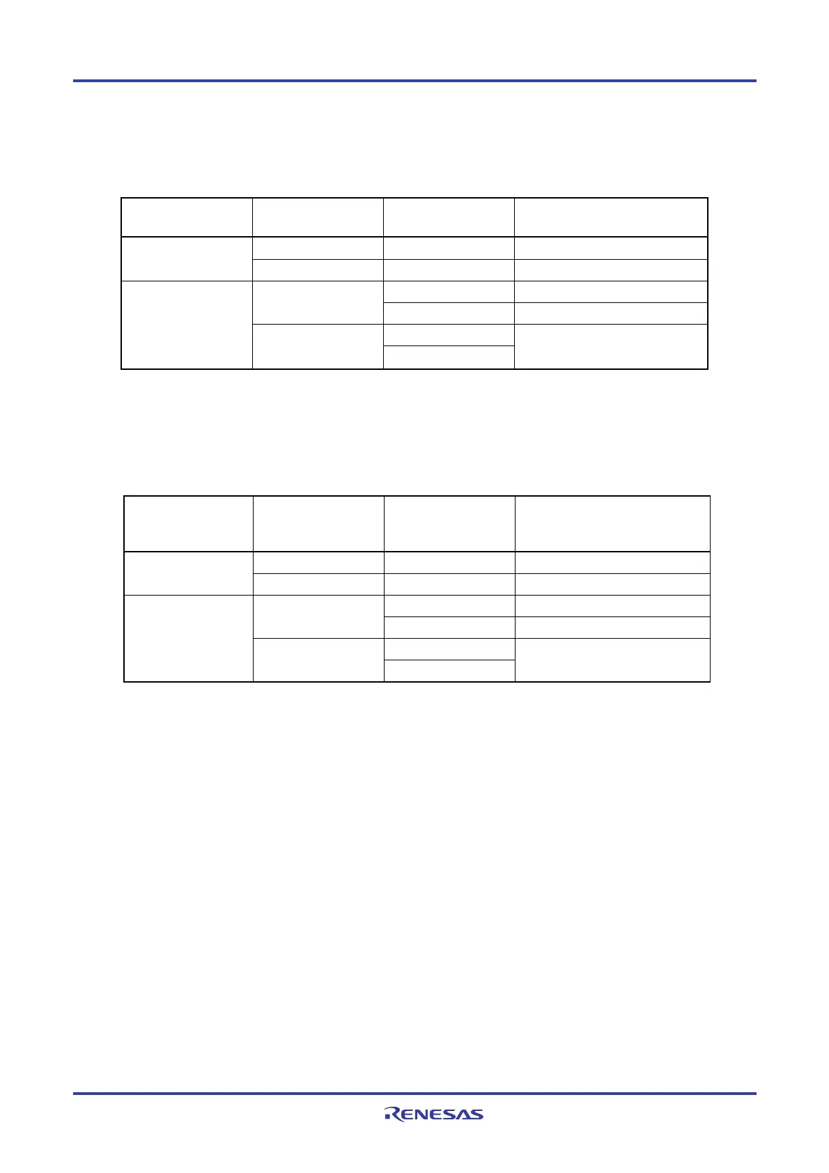
The ANI0/P20 to ANI7/P27 and ANI8/P150 to ANI14/P156 pins are as shown below depending on the settings of the
A/D port configuration register (ADPC), analog input channel specification register (ADS), PM2 and PM15 registers.
Table 11-4. Setting Functions of ANI0/P20 to ANI7/P27, ANI8/P150 to ANI14/P156 Pins
ADPC PM2, PM15 ADS
ANI0/P20 to ANI7/P27,
ANI8/P150 to ANI14/P156 Pins
Input mode
−
Digital input Digital I/O selection
Output mode
−
Digital output
Selects ANI. Analog input (to be converted) Input mode
Does not select ANI. Analog input (not to be converted)
Selects ANI.
Analog input selection
Output mode
Does not select ANI.
Setting prohibited
The ANI16 to ANI26 pins are as shown below depending on the settings of port mode control registers 0, 3, 10, 11, 12,
and 14 (PMC0, PMC3, PMC10, PMC11, PMC12, PMC14), analog input channel specification register (ADS), PM0,
PM3, PM10, PM11, PM12, and PM14 registers.
Table 11-5. Setting Functions of ANI16 to ANI26 Pins
PMC0, PMC3, PMC10,
PMC11, PMC12, and
PMC14
PM0, PM3, PM10,
PM11, PM12, and
PM14
ADS ANI16 to ANI26 Pins
Input mode
−
Digital input Digital I/O selection
Output mode
−
Digital output
Selects ANI. Analog input (to be converted) Input mode
Does not select ANI. Analog input (not to be converted)
Selects ANI.
Analog input selection
Output mode
Does not select ANI.
Setting prohibited
<R>
 Loading...


