RL78/G13 CHAPTER 12 SERIAL ARRAY UNIT
R01UH0146EJ0100 Rev.1.00 673
Sep 22, 2011
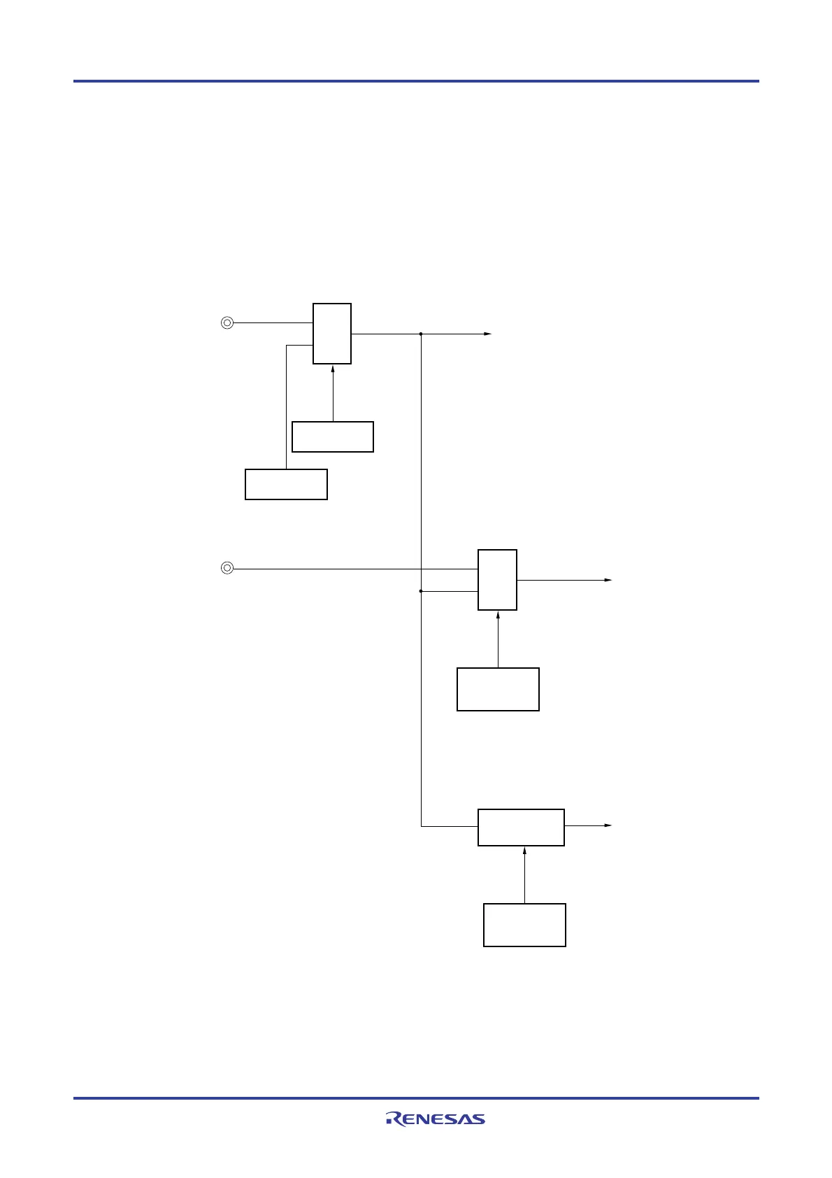
Figure 12-102 and figure 12-103 show the configuration of a port that manipulates reception of LIN.
The wakeup signal transmitted from the master of LIN is received by detecting an edge of an external interrupt (INTP0).
The length of the sync field transmitted from the master can be measured by using the external event capture operation of
the timer array unit 0 to calculate a baud-rate error.
By controlling switch of port input (ISC0/ISC1), the input source of port input (RxD2) for reception can be input to the
external interrupt pin (INTP0) and timer array unit
Figure 12-102 Port Configuration for Manipulating Reception of LIN (30, 32, 36, 40-pin)
RXD2 input
INTP0 input
Channel 7 input of TAU
P14/RxD2/SI20/SDA20
P137/INTP0
Port input
switch control
(ISC0)
<ISC0>
0: Selects INTP0 (P137)
1: Selects RxD2 (P14)
Port mode
(PM14)
Output latch
(P14)
Port input
switch control
(ISC1)
<ISC1>
0: Do not use a timer input signal for channel 7.
1: Selects RxD2 (P14)
Input controller
Selector
Selector
Remark ISC0, ISC1: Bits 0 and 1 of the input switch control register (ISC) (See Figure 12-19.)

 Loading...


