RL78/G13 CHAPTER 16 INTERRUPT FUNCTIONS
R01UH0146EJ0100 Rev.1.00 824
Sep 22, 2011
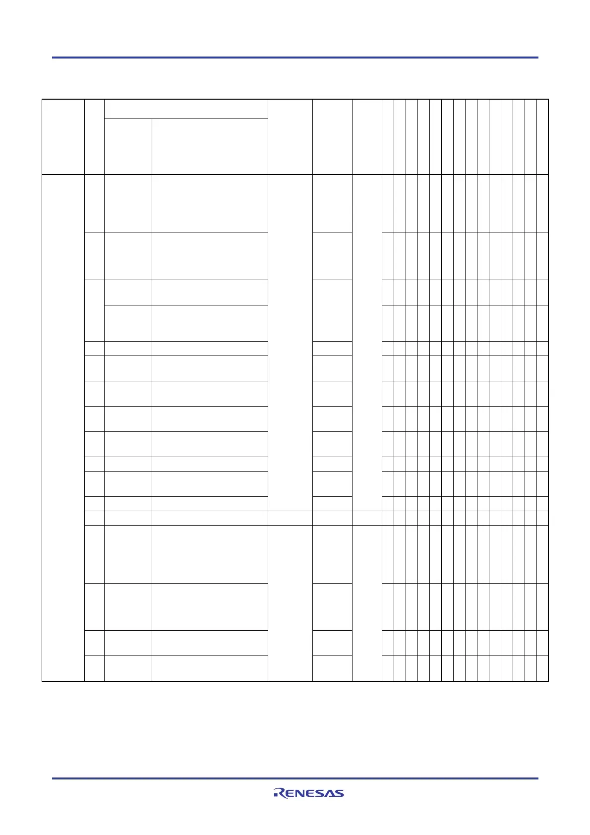
Table 16-1. Interrupt Source List (2/4)
Interrupt Source
Interrupt
Type
Default Priority
Note 1
Name Trigger
Internal/
External
Vector
Table
Address
Basic Configuration
Type
Note 2
128-pin
100-pin
80-pin
64-pin
52-pin
48-pin
44-pin
40-pin
36-pin
32-pin
30-pin
25-pin
24-pin
20-pin
16 INTST1/
INTCSI10/
INTIIC10
UART1 transmission transfer
end or buffer empty
interrupt/CSI10 transfer end or
buffer empty interrupt
/IIC10
transfer end
0024H √ √ √ √
Note 3
Note 3
Note 3
Note 3
Note 3
Note 3
Note 3
Note 3
Note 3
Note 3
17 INTSR1/
INTCSI11/
INTIIC11
UART1 reception transfer
end/CSI11 transfer end or
buffer empty interrupt
/IIC11
transfer end
0026H √ √ √ √ √ √ √ √ √ √ √ √ √ √
INTSRE1
UART1 reception
communication error occurrence
√ √ √ √ √ √ √ √ √ √ √ √ √ √18
INTTM03H End of timer channel 3 count or
capture (at 8-bit timer
operation)
0028H
√ √ √ √ √ √ √ √ √ √ √ √ √ √
19 INTIICA0 End of IICA0 communication 002AH √ √ √ √ √ √ √ √ √ √ √ √ √ −
20 INTTM00 End of timer channel 0 count or
capture
002CH √ √ √ √ √ √ √ √ √ √ √ √ √ √
21 INTTM01 End of timer channel 1 count
or capture
002EH √ √ √ √ √ √ √ √ √ √ √ √ √ √
22 INTTM02 End of timer channel 2 count
or capture
0030H √ √ √ √ √ √ √ √ √ √ √ √ √ √
23 INTTM03 End of timer channel 3 count
or capture
0032H √ √ √ √ √ √ √ √ √ √ √ √ √ √
24 INTAD End of A/D conversion 0034H √ √ √ √ √ √ √ √ √ √ √ √ √ √
25 INTRTC Fixed-cycle signal of real-time
clock/alarm match detection
0036H √ √ √ √ √ √ √ √ √ √ √ √ √ √
26 INTIT Interval signal detection
Internal
0038H
(A)
√ √ √ √ √ √ √ √ √ √ √ √ √ √
27 INTKR Key return signal detection External 003AH (C) √ √ √ √ √ √ √ √ − − − − − −
28 INTST3/
INTCSI30/
INTIIC30
UART3 transmission transfer
end or buffer empty
interrupt/CSI30 transfer end or
buffer empty interrupt
/IIC30
transfer end
003CH √ √ √ − − − − − − − − − − −
29 INTSR3/
INTCSI31/
INTIIC31
UART3 reception transfer
end/CSI31 transfer end or
buffer empty interrupt
/IIC31
transfer end
003EH √ √ √ − − − − − − − − − − −
30 INTTM13 End of timer channel 13 count
or capture
0040H √ √ √ − − − − − − − − − − −
Maskable
31 INTTM04 End of timer channel 4 count
or capture
Internal
0042H
(A)
√ √ √ √ √ √ √ √ √ √ √ √ √ √
Notes 1. The default priority determines the sequence of interrupts if two or more maskable interrupts occur
simultaneously. Zero indicates the highest priority and 53 indicates the lowest priority.
2. Basic configuration types (A) to (D) correspond to (A) to (D) in Figure 16-1.
3. INTST1 only.

 Loading...


