RL78/G13 CHAPTER 16 INTERRUPT FUNCTIONS
R01UH0146EJ0100 Rev.1.00 826
Sep 22, 2011
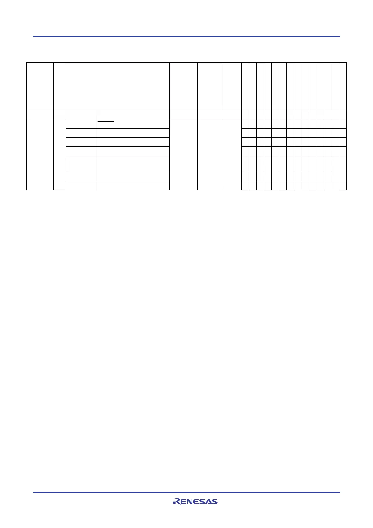
Table 16-1. Interrupt Source List (4/4)
Interrupt
Type
Default Priority
Note 1
Interrupt Source
Internal/
External
Vector
Table
Address
Basic Configuration
Type
Note 2
128-pin
100-pin
80-pin
64-pin
52-pin
48-pin
44-pin
40-pin
36-pin
32-pin
30-pin
25-pin
24-pin
20-pin
Software − BRK Execution of BRK instruction − 007EH (D) √ √ √ √ √ √ √ √ √ √ √ √ √ √
RESET RESET pin input √ √ √ √ √ √ √ √ √ √ √ √ √ √
POR Power-on-reset √ √ √ √ √ √ √ √ √ √ √ √ √ √
LVD Voltage detection
Note 3
√ √ √ √ √ √ √ √ √ √ √ √ √ √
WDT Overflow of watchdog timer √ √ √ √ √ √ √ √ √ √ √ √ √ √
TRAP Execution of illegal
instruction
Note 4
√ √ √ √ √ √ √ √ √ √ √ √ √ √
IAW Illegal-memory access √ √ √ √ √ √ √ √ √ √ √ √ √ √
Reset −
RAMTOP RAM parity error
− 0000H −
√ √ √ √ √ √ √ √ √ √ √ √ √ √
Notes 1. The default priority determines the sequence of interrupts if two or more maskable interrupts occur
simultaneously. Zero indicates the highest priority and 53 indicates the lowest priority.
2. Basic configuration types (A) to (D) correspond to (A) to (D) in Figure 16-1.
3. When bit 7 (LVIMD) of the voltage detection level register (LVIS) is set to 1.
4. When the instruction code in FFH is executed.
Reset by the illegal instruction execution not issued by emulation with the in-circuit emulator or on-chip
debug emulator.
<R>

 Loading...


