RL78/G13 CHAPTER 16 INTERRUPT FUNCTIONS
R01UH0146EJ0100 Rev.1.00 834
Sep 22, 2011
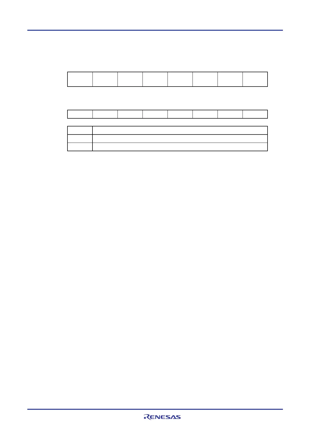
Figure 16-2. Format of Interrupt Request Flag Registers (IF0L, IF0H, IF1L, IF1H, IF2L, IF2H, IF3L) (128-pin) (2/2)
Address: FFFD1H After reset: 00H R/W
Symbol <7> <6> <5> <4> <3> <2> <1> <0>
IF2H FLIF IICAIF1 MDIF
SREIF3
TMIF13H
TMIF12 TMIF11 TMIF10 PIF11
Address: FFFD2H After reset: 00H R/W
Symbol 7 6 <5> <4> <3> <2> <1> <0>
IF3L 0 0 TMIF17 TMIF16 TMIF15 TMIF14 DMAIF3 DMAIF2
XXIFX Interrupt request flag
0 No interrupt request signal is generated
1 Interrupt request is generated, interrupt request status
Cautions 1. The above is the bit layout for the 128-pin. The available bits differ depending on the product.
For details about the bits available for each product, see Table 16-2. Be sure to clear bits that
are not available to 0.
2. When operating a timer, serial interface, or A/D converter after standby release, operate it once
after clearing the interrupt request flag. An interrupt request flag may be set by noise.
3. When manipulating a flag of the interrupt request flag register, use a 1-bit memory manipulation
instruction (CLR1). When describing in C language, use a bit manipulation instruction such as
“IF0L.0 = 0;” or “_asm(“clr1 IF0L, 0”);” because the compiled assembler must be a 1-bit memory
manipulation instruction (CLR1).
If a program is described in C language using an 8-bit memory manipulation instruction such as
“IF0L &= 0xfe;” and compiled, it becomes the assembler of three instructions.
mov a, IF0L
and a, #0FEH
mov IF0L, a
In this case, even if the request flag of the another bit of the same interrupt request flag register
(IF0L) is set to 1 at the timing between “mov a, IF0L” and “mov IF0L, a”, the flag is cleared to 0
at “mov IF0L, a”. Therefore, care must be exercised when using an 8-bit memory manipulation
instruction in C language.
(2) Interrupt mask flag registers (MK0L, MK0H, MK1L, MK1H, MK2L, MK2H, MK3L)
The interrupt mask flags are used to enable/disable the corresponding maskable interrupt servicing.
The MK0L, MK0H, MK1L, MK1H, MK2L, MK2H, and MK3L registers can be set by a 1-bit or 8-bit memory
manipulation instruction. When the MK0L and MK0H registers, the MK1L and MK1H registers, and the MK2L and
MK2H registers are combined to form 16-bit registers MK0, MK1, and MK2, they can be set by a 16-bit memory
manipulation instruction.
Reset signal generation sets these registers to FFH.
Remark If an instruction that writes data to this register is executed, the number of instruction execution clocks
increases by 2 clocks.

 Loading...


