ECODRIVE03-SGP-03VRS Description of Diagnostic Messages F… and E… 4-23
DOK-ECODR3-SGP-03VRS**-WA01-EN-P
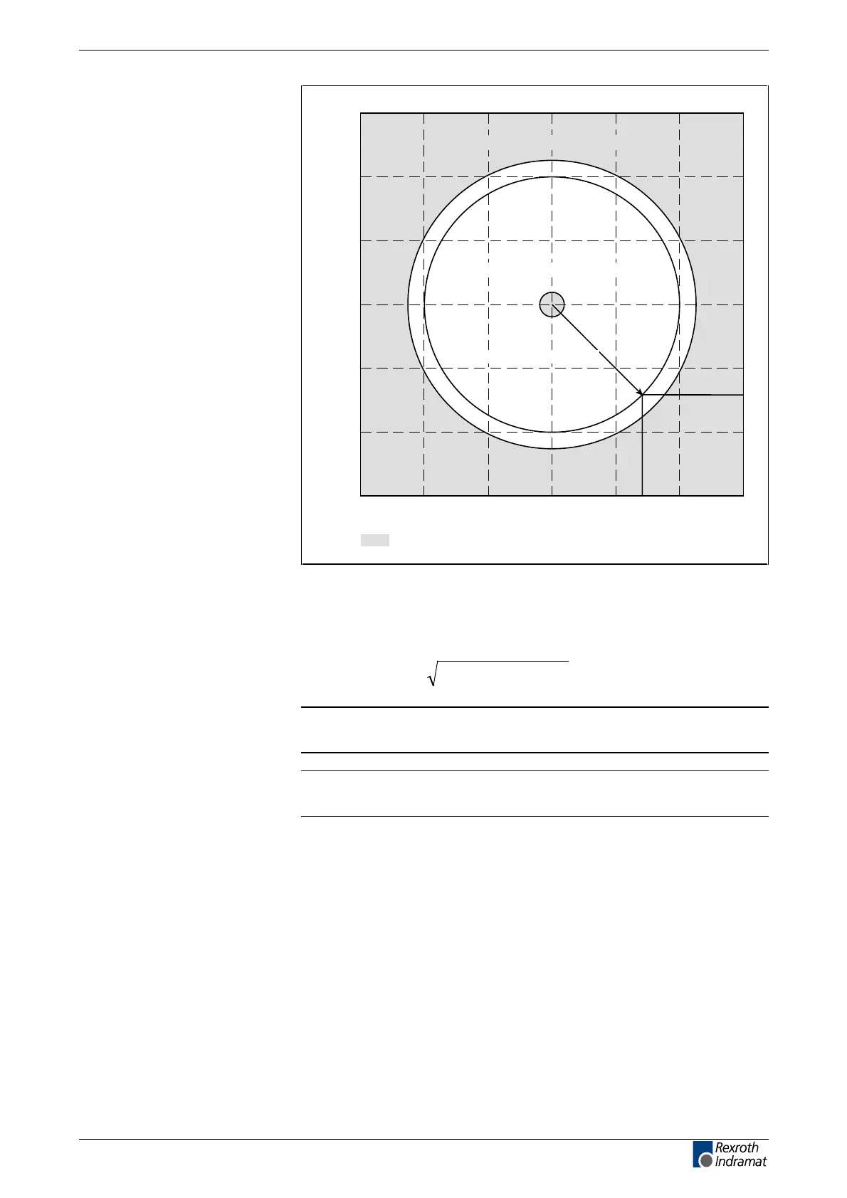
Permissible signal amplitudes for sine and cosine signals
cosine signal amplitude
15
10
0
-5
-10
5
-15
-15 -10 -5 0 5 10 15
sine signal amplitude
Dg5004a1.fh7
nominal pointer length (9.2 V)
minimum pointer length > 5.0 or 1.0 V
maximum pointer length > 11.8 V
=non-permissible range
Fig. 4-5: Correct signal amplitude
Example:
Ucos = -6,5 V
Usin = 6,5 V
()
V9.26.5V6.5Vlength pointer
2
2
≈+−=
Note: The error cannot be cleared in communications phase 4. Before
clearing the error, switch to communications phase 2.
Note: When an incremental encoder with squarewave signals is
used, the signal is not monitored.
Cause:
1. Defective encoder cable
2. Disruptive electro-magnetic interference on the encoder cable
3. Defective encoder
Remedy:
1. Check the measurement system cable.
2. Lay the feedback cable well away from the motor power cable. The
cover must be placed over the drive controller (see drive controller
project specifications.)
3. Check the measurement system and exchange, if necessary.