SPIROR HP - DR
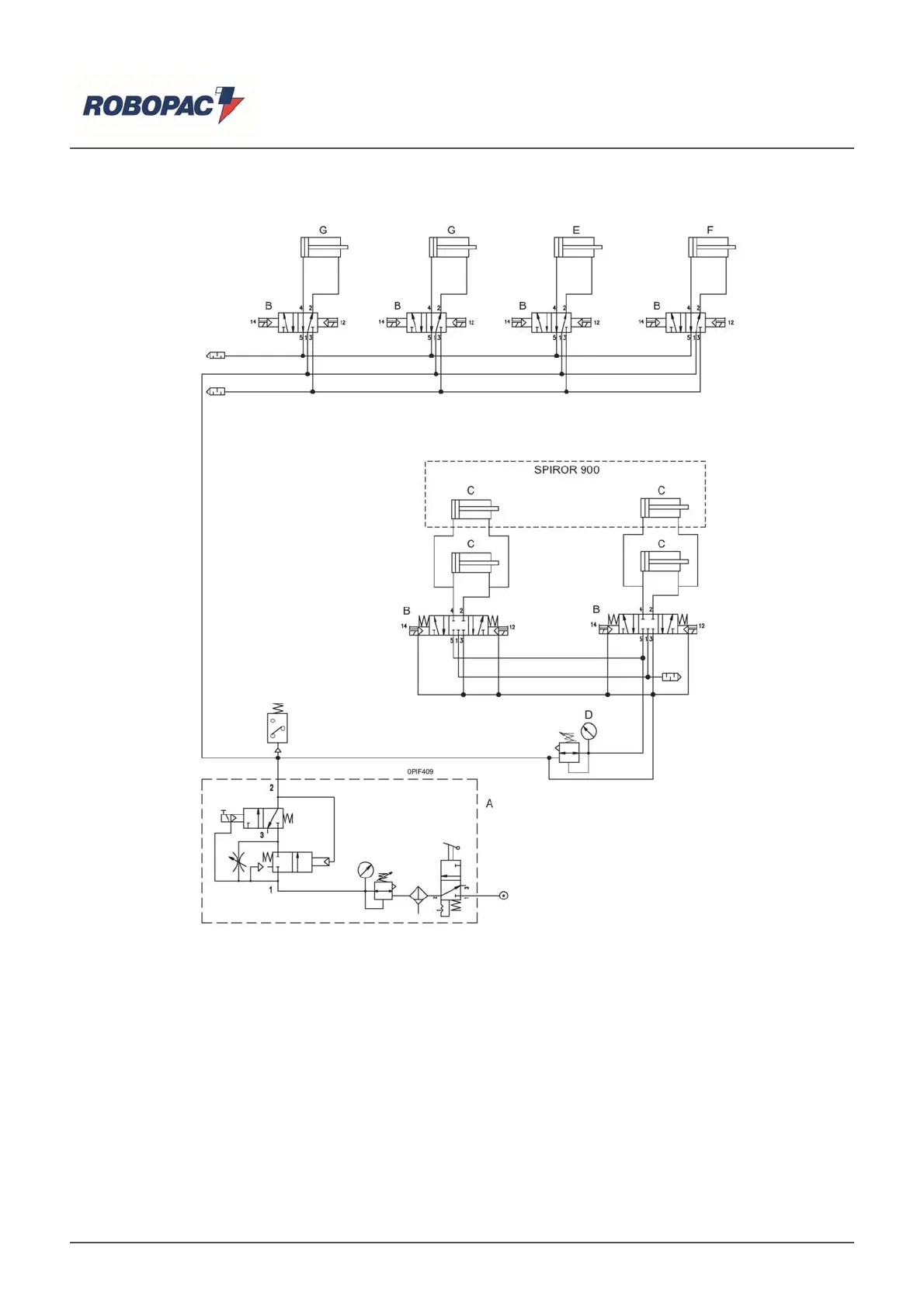
10.2. PNEUMATIC CIRCUIT DIAGRAM SPIROR HP
Ke
) Air treatment unit.
B) Solenoid valve.
C) Presser drive pneumatic cylinder.
D) Adjust / Pressure units thrust manometer.
E) Open/close clamp pneumatic cylinder.
F) Pneumatic cylinder forward / clamp backward.
G) Self-centring guides pneumatic cylinder (optional).
English