Publication 2094-UM001A-EN-P — September 2006
Connecting the Kinetix 6000 Drive System 101
Wiring the Motor/Resistive Brake (BC) Connector
This example applies to axis modules (AM) and the inverter section of
integrated axis modules (IAM).
Integrated Axis Module/Axis Module (BC connector)
Wiring 24V dc Brake Input Power Connections
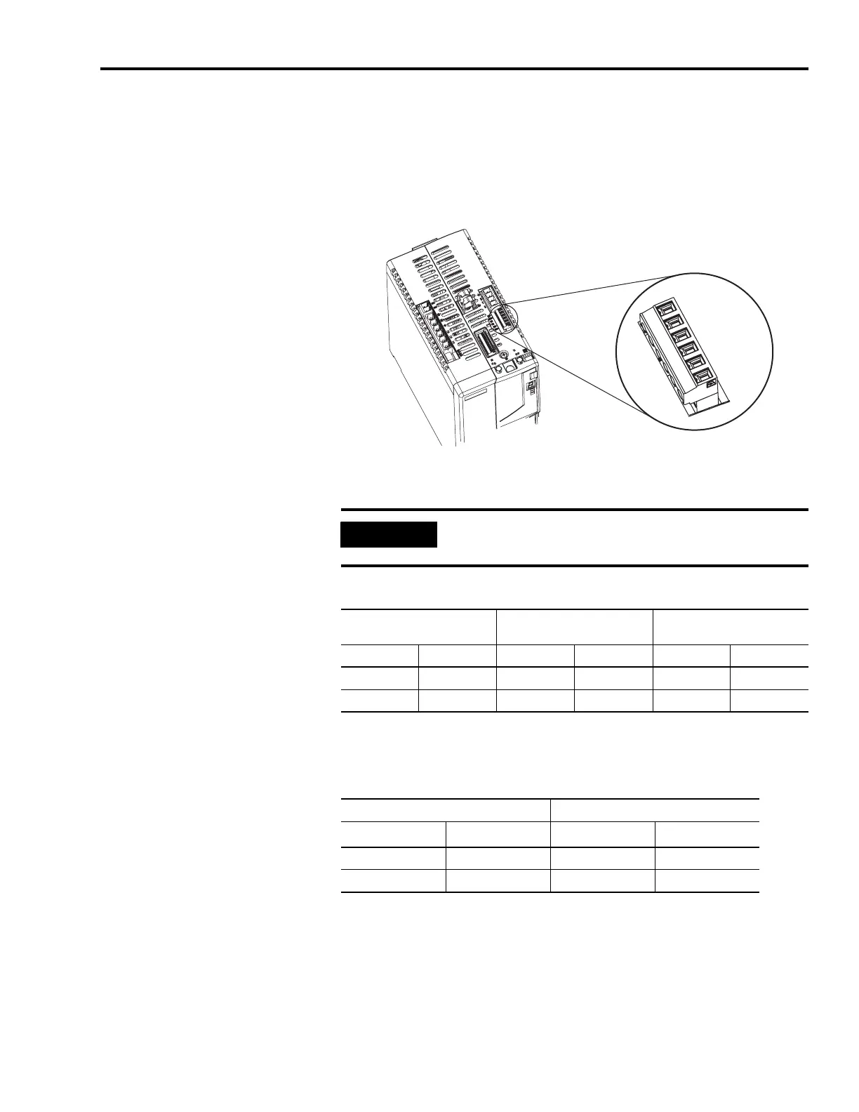
Motor/Resistive Brake (BC) Connector
Wiring the Resistive Brake Module (RBM) Connections
Motor/Resistive Brake (BC) Connector
Integrated Axis Module, Top View
(2094-BC02-M02-S is shown)
MBRK-
MBRK+
COM
PWR
DBRK-
DBRK+
1 2 3 4 5 6
Motor/Resistive Brake
(BC) Connector
IMPORTANT
If your system includes a line interface module (LIM), you can
source the 24V dc from the LIM (P1L or PSL connector).
2094-ALxxS, -BLxxS,
-XL75S-Cx
2094-AL09 and -BL02 BC Connector (IAM/AM)
P1L Pin Signal PSL Pin Signal BC Pin Signal
1IO_PWR21MBRK PWR3PWR
2 IO_COM2 2 MBRK COM 4 COM
RBM I/O Connections BC Connector (IAM/AM)
TB3 Pin Signal MP Pin
Signal
(1)
(1)
Firmware version 1.071 or later, is required to use the DBRK outputs on the Kinetix 6000 IAM/AM.
6 COIL_A1 1 DBRK+
7 COIL_A2 2 DBRK-

 Loading...


