Publication 2094-UM001A-EN-P — September 2006
Kinetix 6000 Connector Data 55
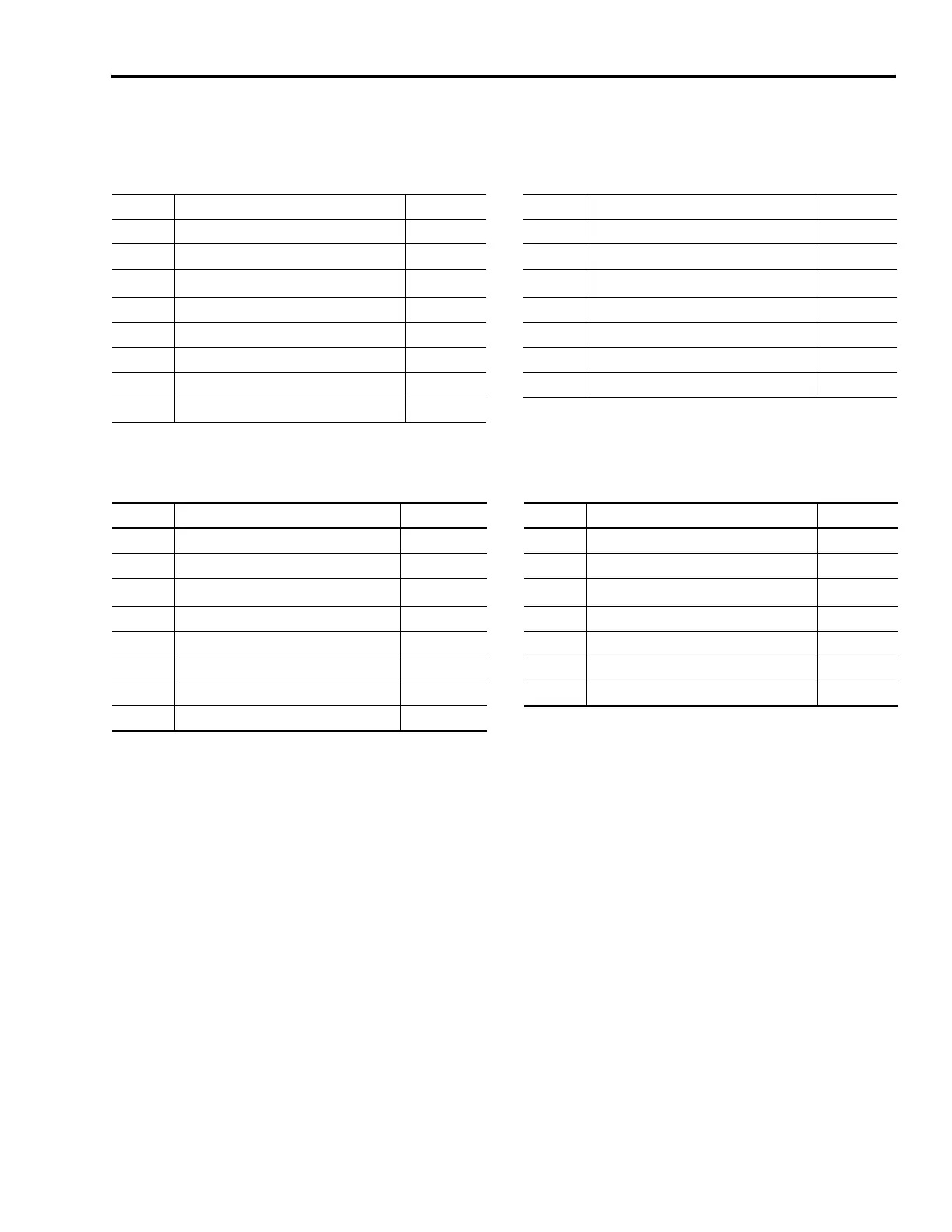
Motor Feedback Connector Pinouts
Stegmann Hiperface (SRS/SRM)
TTL or Sine/Cosine with Index Pulse and Hall Commutation
MF Pin Description Signal MF Pin Description Signal
1 Sine differential input+ SINE+ 9 Reserved —
2 Sine differential input- SINE- 10 Hiperface data channel DATA-
3 Cosine differential input+ COS+ 11
Motor thermal switch (normally closed)
(1)
TS
4 Cosine differential input- COS- 12 Reserved —
5 Hiperface data channel DATA+ 13 Reserved —
6 Common ECOMM 14 Encoder power (+5V) EPWR_5VM
7 Encoder power (+9V) EPWR_9VM 15 Reserved —
8Reserved —
(1)
Not applicable unless motor has integrated thermal protection.
MF Pin Description Signal MF Pin Description Signal
1 AM+ / Sine differential input+ AM+ / SINE+ 9 Reserved —
2 AM- / Sine differential input- AM- / SINE- 10 Index pulse- IM-
3 BM+ / Cosine differential input+ BM+ / COS+ 11
Motor thermal switch (normally closed)
(1)
TS
4 BM- / Cosine differential input- BM- / COS- 12 Single-ended 5V hall effect commutation S1
5 Index pulse+ IM+ 13 Single-ended 5V hall effect commutation S2
6 Common ECOMM 14 Encoder power (+5V) EPWR_5VM
7 Encoder power (+9V) EPWR_9VM 15 Reserved —
8 Single-ended 5V hall effect commutation S3
(1)
Not applicable unless motor has integrated thermal protection.

 Loading...


